Electric wheelchair control system and electric wheelchair control method

a control system and electric wheelchair technology, applied in the direction of motor/generator/converter stopper, dynamo-electric converter control, electric devices, etc., can solve the problems of occupants not being able to minimize the wheelchair brake, difficult control of wheelchairs, and discomfort of occupants

Active Publication Date: 2020-04-23
IND TECH RES INST
View PDF0 Cites 0 Cited by
  • Summary
  • Abstract
  • Description
  • Claims
  • Application Information

AI Technical Summary

Benefits of technology

[0009]In view of the above description, the controller can automatically output a PWM drive signal to the motor driver to drive a rotation of the three-phase AC motor when the wheelchair travels on a sloped ground and an external force applied by a occupant to the wheel assembly is toward the front end of the chair. The three-phase AC motor wheel assembly can drive the wheel assembly to rotate when it rotates. Therefore, the wheelchair still moves forward along the sloped ground even if the occupant does not exert any force to push the wheel assembly. Conversely, the controller can automatically output a PWM braking signal to the motor driver to restrain the rotation of the three-phase AC motor when the wheelchair travels on the sloped ground and the external force applied by the occupant to the wheel assembly is toward the rear end of the chair. As a result, the wheelch...

Problems solved by technology

When the wheelchair travels on a sloped ground, the sliding force of the wheelchair will cause the wheelchair to accelerate, which makes an occupant control the wheelchair difficultly, so that the occupant must need a caregiver to drive the wheelchair.
However, the hydraulic and electronic brakes have certain volumes, so it is harmful to the minimizing the wheelchair brake.
Another t...

Method used


Image

  • Electric wheelchair control system and electric wheelchair control method
  • Electric wheelchair control system and electric wheelchair control method
  • Electric wheelchair control system and electric wheelchair control method

Examples


Embodiment Construction

[0022]In the following detailed description, for purposes of explanation, numerous specific details are set forth in order to provide a thorough understanding of the disclosed embodiments. It will be apparent, however, that one or more embodiments may be practiced without these specific details. In other instances, well-known structures and devices are schematically shown in order to simplify the drawings.

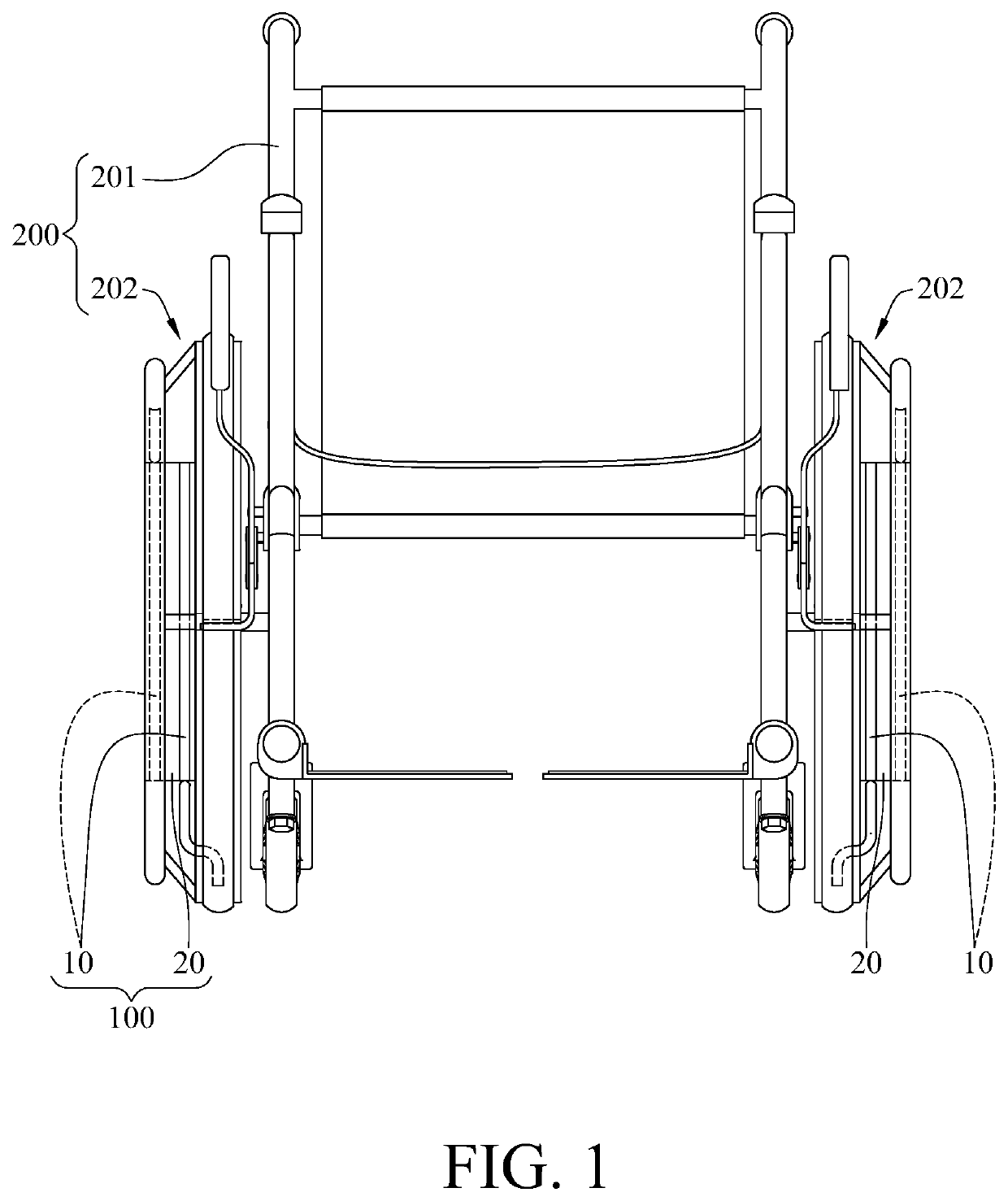
[0023]Please refer to FIG. 1 which is a schematic view of an electric wheelchair control system assembled with a wheelchair according an embodiment of the present disclosure. The electric wheelchair control system 100 is applied to control a wheelchair 200, the electric wheelchair control system 100 includes two sensing assemblies 10 and two power devices 20, and the wheelchair 200 includes a chair 201 and a pair of wheel assemblies 202. The two sensing assemblies 10 are respectively assembled with the two wheel assemblies 202, and each of the power devices 20 is configured to conn...


PUM


Abstract

An electric wheelchair control system is adapted to control a wheelchair and comprises a sensing assembly, an inertial sensor, a controller, a motor driver, and a three-phase AC motor. The sensing assembly is configured to detect an external force applied to the wheelchair and generate a first sensed signal based thereon. The inertial sensor is configured to detect an inclination of the wheelchair and generate a second sensed signal based thereon. The controller selectively outputs a PWM braking signal to the motor driver according to the first sensed signal and the second sensed signal, and the PWM braking signal includes an upper arm braking signal and a lower arm braking signal, wherein the upper arm braking signal and the lower arm braking signal have the same duty cycle and when the upper arm braking signal is at a high level, the lower arm braking signal is at a low level.

Description

CROSS-REFERENCE TO RELATED APPLICATIONS[0001]This non-provisional application claims priority under 35 U.S.C. § 119(a) on Patent Application No(s). 107136594 filed in Republic of China on Oct. 17, 2018, the entire contents of which are hereby incorporated by reference.BACKGROUND1. Technical Field[0002]This disclosure relates to a motor control system, especially for a motor control system and a method thereof adapted to a wheelchair.2. Related Art[0003]A wheelchair is an important walker tool for the elderly or disabled person. When the wheelchair travels on a sloped ground, the sliding force of the wheelchair will cause the wheelchair to accelerate, which makes an occupant control the wheelchair difficultly, so that the occupant must need a caregiver to drive the wheelchair.[0004]At present, wheelchair brakes have multiple types. One type of the wheelchair brakes has a slope sensor which can be used to know an inclination of a ground by the slope sensor. When the ground is detected...

Claims


Application Information

Patent Timeline
IPC IPC(8): A61G5/10H02P3/18A61G5/04B60L15/20
CPCB60L2240/42B60L2220/42B60L15/2018B60L2240/12A61G5/045B60L2220/10A61G5/1008A61G2203/42B60L2200/34A61G5/1032H02P3/18A61G5/1035A61G5/1051A61G5/04A61G2203/10A61G5/048Y02T10/72Y02T10/64
Inventor LIN, YI-LING
Owner IND TECH RES INST
Why Eureka
Try Eureka