Testing system for ultrasonic imaging system

a testing system and ultrasound technology, applied in ultrasonic/sonic/infrasonic diagnostics, instruments, applications, etc., can solve the problems of affecting affecting the accuracy of ultrasound systems, and few defective receive channels in the acoustic system itself. achieve the effect of reducing alignment requirements, rapid and precise alignment, and assessing the accuracy or correctness of ultrasound systems

Inactive Publication Date: 2020-09-24
ACERTARA ACOUSTIC LAB
View PDF0 Cites 0 Cited by
  • Summary
  • Abstract
  • Description
  • Claims
  • Application Information

AI Technical Summary

Benefits of technology

[0008]In view of at least the foregoing, the inventors have determined that an objective solution that is repeatable by multiple users with reduced alignment requirements and with digital record storage is needed. Broadly, disclosed herein is a system for use in testing ultrasound systems that includes a tissue mimicking phantom and computer-readable instructions that are configured to automatically compare (e.g., on a pixel by pixel basis) images of the phantom obtained by the ultrasound system to one or more reference images (e.g., indicating how the obtained images should appear) and provide output that assists personnel in assessing the accuracy or correctness of the ultrasound system. Modern manufacturing techniques may be used to place precise structures inside of the phantom to allow for both passive and active evaluation of the probe and its constituent pieces in a manner previously unattainable. Known structure geometry, measured probe output, and injected signals of a known magnitude may be incorporated.
[0009]In one arrangement, any appropriate digital recording device may be used to digitally store signals received from one or more ou...

Problems solved by technology

In the case of ultrasound probes, for instance, the failure of a small number of elements in a given array, or a few defective receive channels in the acoustic system itself, may not be readily perceptible to users because of the averaging effect of summing many elements to form an acoustic beam.
But the failure of even a small number of elements or receive channels can significantly degrade the performance of acoustic imaging systems, notably in certain modes of operation like those known as “Doppler” or “near-field” imaging modes.
In addition to the inherent subjectivity present in this arrangement, however, the number of people a...

Method used


Image

  • Testing system for ultrasonic imaging system
  • Testing system for ultrasonic imaging system
  • Testing system for ultrasonic imaging system

Examples


Embodiment Construction

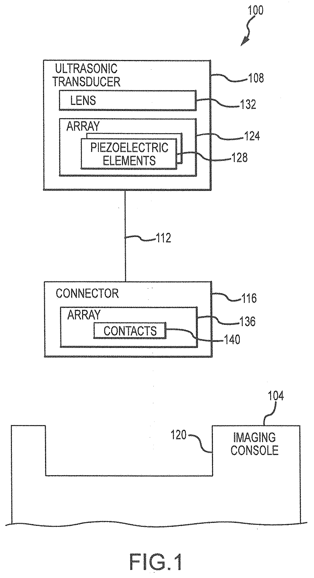
[0020]Disclosed herein is a system for testing performance characteristics of ultrasound systems that substantially removes the inherent subjectivity in existing manners of obtaining tissue mimicking phantom measurements, increases the pool of available testing personnel, reduces the number of false-positive and false-negative test results that are caused by faulty equipment, and digitizes testing records to create opportunities for testing to be performed quickly on a daily or even a case-by-case basis. Before discussing the testing system in more detail, reference is made to FIG. 1 which presents a block diagram of one type of ultrasonic imaging system 100 with which the testing system disclosed herein may be utilized. Broadly, the system 100 may include an imaging console 104 and an ultrasonic transducer 108 (e.g., transducer head) that is electrically interconnectable to the imaging console 104 by any appropriate cable assembly 112 and a connector or connector assembly 116, wher...


PUM


Abstract

A system for use in testing ultrasound systems that includes a tissue mimicking phantom and computer-readable instructions that are configured to automatically compare images of the phantom obtained by the ultrasound system to one or more reference images (e.g., indicating how the obtained images should appear) and provide output that assists personnel in assessing the operationality of the ultrasound system. Any appropriate digital recording device may be used to digitally store signals received from outputs of the ultrasound system for use by the image comparison module on a real-time basis or after full acquisition of the phantom images.

Description

FIELD OF THE INVENTION[0001]This application generally relates to ultrasound systems and, more particularly, to the testing of ultrasound systems.BACKGROUND OF THE INVENTION[0002]Transmission of pressure waves such as acoustic radiation toward a target and reception of the scattered radiation may be managed by a modern acoustic-imaging system, which may take a variety of forms. For instance, acoustic imaging is an important technique that may be used at different acoustic frequencies for varied applications that range from medical imaging to nondestructive testing of structures. The techniques generally rely on the fact that different structures have different acoustic impedances, allowing characterization of structures and their interfaces from information embodied by the different scattering patterns that result. While most applications use radiation reflected from structures, some techniques also make use of information in transmitted patterns.[0003]For example, many modern syste...

Claims


Application Information

Patent Timeline
IPC IPC(8): A61B8/00G01N29/44G01N29/30
CPCG09B23/286A61B8/587G01N29/4427G01N29/30G01N2291/02475G01N29/0654G09B23/30
Inventor MOORE, LEVIBROWN, ROBERTTIMMS, CONNOR
Owner ACERTARA ACOUSTIC LAB
Why Eureka
Try Eureka