HVAC systems with evaporator bypass and supply air recirculation and methods of using same

a technology of evaporator bypass and supply air recirculation, which is applied in the field of hvac systems, can solve the problems of over-cooling of conditioned air, damage to components of hvac systems, waste of energy, etc., and achieve the effects of reducing energy waste, reducing unnecessary cooling of flow, and effectively removing moistur

Active Publication Date: 2020-09-24
LENNOX IND
View PDF0 Cites 2 Cited by
  • Summary
  • Abstract
  • Description
  • Claims
  • Application Information

AI Technical Summary

Benefits of technology

[0007]Certain embodiments provide one or more technical advantages including or in addition to those described above. For example, an embodiment reduces energy waste by reducing unnecessary cooling of the flow of air to achieve a desired relative humidity. As another example, an embodiment allows a portion of the flow of air from the return air duct to bypass the evaporator coil so that evaporator coil may more effectively remove moisture from the flow of air while at the same time maintaining adequate ventilation airflow needs in the conditioned space. Certain embodiments may include none, some, or all of the above technical advantages. One or more other technical advantages may be readily apparent to one skilled in the art from the figures, descriptions, and claims included herein.

Problems solved by technology

However, dehumidification using conventional HVAC systems is far from optimal and can result in over-cooling of the conditioned air, waste of energy, and damage to components of the HVAC system, as described in greater detail herein.

Method used


Image

  • HVAC systems with evaporator bypass and supply air recirculation and methods of using same
  • HVAC systems with evaporator bypass and supply air recirculation and methods of using same
  • HVAC systems with evaporator bypass and supply air recirculation and methods of using same

Examples


Embodiment Construction

[0013]Embodiments of the present disclosure and its advantages are best understood by referring to FIGS. 1 through 5 of the drawings, like numerals being used for like and corresponding parts of the various drawings.

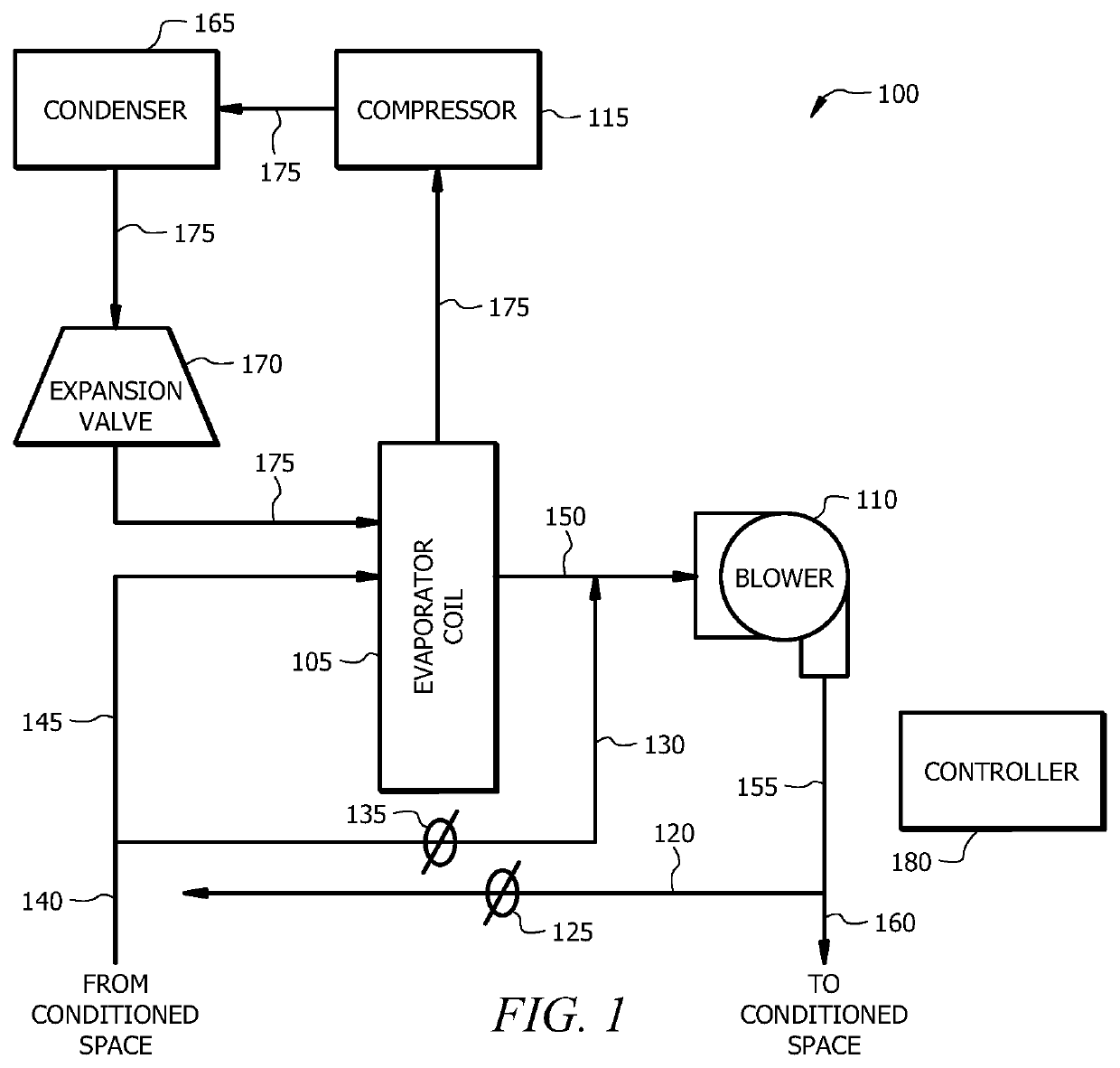
[0014]As described above, HVAC systems are typically configured to supply an enclosed space with conditioned air that is comfortable for occupants of the space. The air supplied by the HVAC system has an associated temperature and an associated relative humidity. In some HVAC systems, the temperature and / or humidity of the supply air may be adjusted (e.g., using a thermostat) in order to meet the occupant's desired comfort.

[0015]However, dehumidification using conventional HVAC systems is far from optimal. This is because an HVAC system's ability to dehumidify air in an enclosed space is tied to the extent to which the HVAC system cools the air in the enclosed space. Indeed, HVAC systems remove moisture from the air by circulating moisturized air over and / or through evap...


PUM


Abstract

An HVAC system includes an evaporator coil disposed between a return air duct and a supply air duct. The system includes a compressor fluidically connected to the evaporator coil, and a blower for providing a flow of air through the HVAC system. The HVAC system includes a supply air recirculation line with a recirculation damper and an evaporator bypass line with a bypass damper. A controller of the HVAC determines a recirculation portion of a flow of air and causes the recirculation damper to move to divert the recirculation portion to the recirculation line, so the air recirculates through the HVAC system. The controller determines a bypass portion of a flow of air and causes the bypass damper to move to divert the bypass portion to the bypass line, so the bypass portion does not contact the evaporator coil.

Description

TECHNICAL FIELD[0001]This disclosure relates generally to heating, ventilation, and air conditioning (HVAC) systems and methods of their use. In particular, this disclosure relates to HVAC systems for improved dehumidification of air supplied to an enclosed space.BACKGROUND[0002]Heating, ventilation, and air conditioning (HVAC) systems are used to regulate environmental conditions within an enclosed space. Typically, HVAC systems have a blower, or recirculation fan, that pulls air from an enclosed space through a return duct and pushes the air back into the enclosed space through one or more supply air ducts after conditioning the air (e.g., heating, cooling, humidifying, or dehumidifying the air). HVAC systems generally include a controller to direct operation of the blower and other components of the system. In addition to directing operation of the HVAC system, the controller may be used to monitor various components of the HVAC system to determine if the components are functioni...

Claims


Application Information

Patent Timeline
Patent Type & Authority Applications(United States)
IPC IPC(8): F24F11/81F24F3/14F24F11/65
CPCF24F2110/20F24F3/14F24F2003/144F24F11/65F24F11/81F24F3/1405F24F2110/10F24F1/0035Y02B30/70F24F3/048
Inventor GOEL, RAKESHSATHYAMURTHI, VIJAY
Owner LENNOX IND
Why Eureka
Try Eureka