Touch display panel and touch display device with switchable viewing angles

a touch display panel and display device technology, applied in the field of display technologies, can solve the problems that the single viewing angle mode of the display device cannot meet the needs of users, and achieve the effects of reducing the thickness of the module, reducing production costs, and simplifying production processes

Active Publication Date: 2021-05-20
KUSN INFOVISION OPTOELECTRONICS
View PDF0 Cites 8 Cited by
  • Summary
  • Abstract
  • Description
  • Claims
  • Application Information

AI Technical Summary

Benefits of technology

[0008]In view of the above, the object of the present invention is to provide a touch display panel with switchable viewing angles, which combines the function of switching between wide and narrow viewing angles and the function of in-cell touch, and can realize touch sensing while achieving the switching between wide and narrow viewing angles.
[0029]For the touch display panel and the touch display device with switchable viewing angles provided by the embodiments of the present invention, the common electrode adopts a time multiplexing manner, so that the image display and the touch sensing are alternately performed. By controlling the voltage applied to the viewing angle control electrode, the touch display panel can be freely switched between the wide viewing angle mode and the narrow viewing angle mode, with the function of switching between wide and narrow viewing angles and the function of in-cell touch being combined to realize touch sensing while achieving the switching between wide and narrow viewing angles. Furthermore, it also simplifies the production process, reduces the production cost, and reduces the module thickness.

Problems solved by technology

Therefore, the display device with a single viewing angle mode has been unable to meet the needs of the users.

Method used


Image

  • Touch display panel and touch display device with switchable viewing angles
  • Touch display panel and touch display device with switchable viewing angles
  • Touch display panel and touch display device with switchable viewing angles

Examples


first embodiment

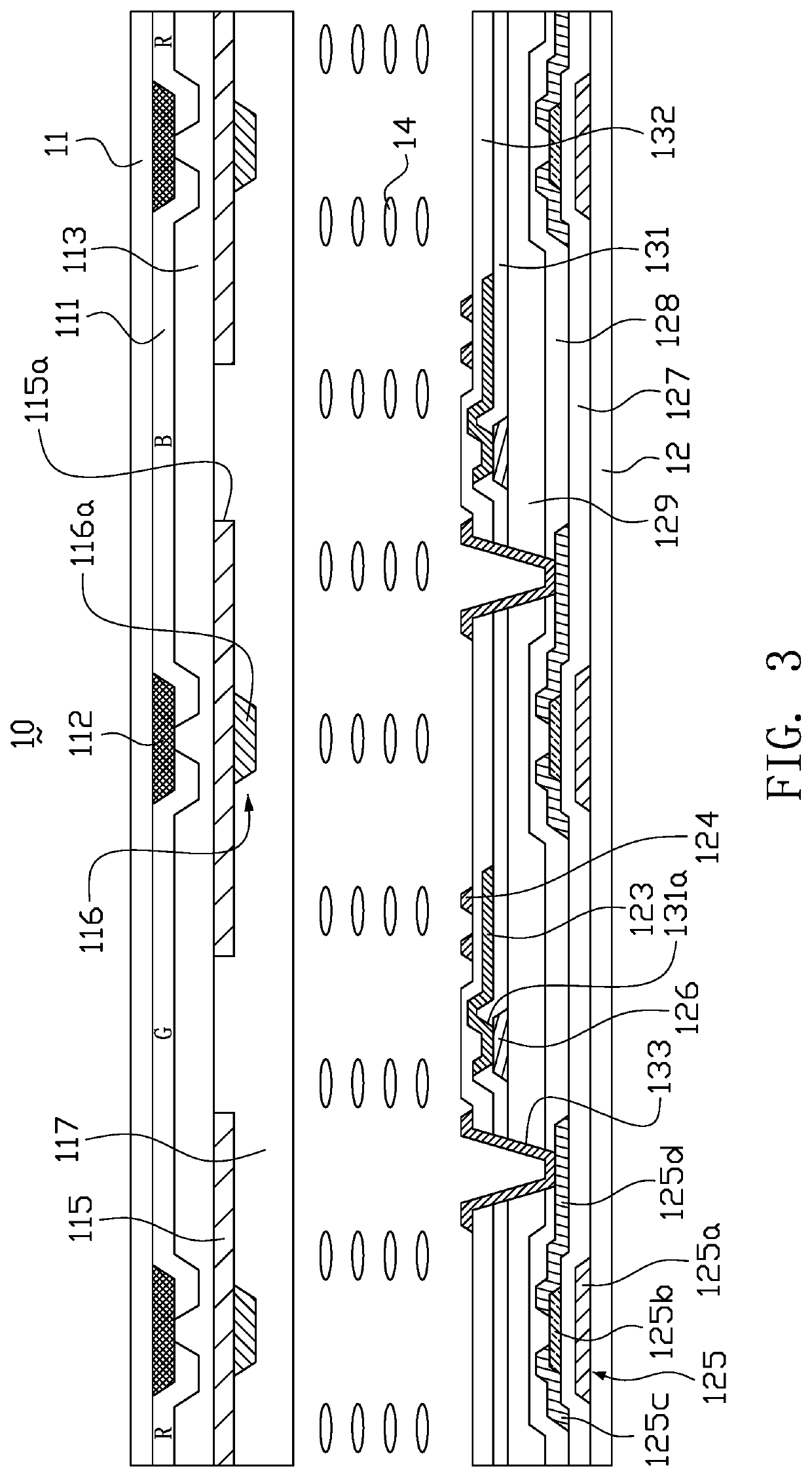
[0044]FIG. 3 is a schematic view of a touch display panel in a wide viewing angle mode according to a first embodiment of the present invention. Referring to FIG. 3, the touch display panel 10 includes a first substrate 11, a second substrate 12 disposed opposite to the first substrate 11, and a liquid crystal layer 14 disposed between the first substrate 11 and the second substrate 12. The first substrate 11 may be a color filter substrate, and the second substrate 12 may be a thin film transistor array substrate.

[0045]In this embodiment, the first substrate 11 is provided with a color filter layer 111, a black matrix (BM) 112, a first overcoat layer 113, a viewing angle control electrode 115, a metal conductive layer 116 and a second overcoat layer 117. The color filter layer 111 includes, for example, color resist materials of three colors of red (R), green (G) and blue (B). The color filter layer 111 and the black matrix 112 are mutually staggered and formed on the surface of th...

second embodiment

[0070]FIG. 10 is a schematic view of a touch display panel according to a second embodiment of the present invention. As shown in FIG. 10, the first substrate 11 is provided with a color filter layer 111, a metal conductive layer 116, a viewing angle control electrode 115 and an overcoat layer 114. The metal conductive layer 116 includes a plurality of metal conductive strips 116a. The metal conductive strips 116a are electrically connected to the viewing angle control electrode 115. This embodiment differs from the foregoing first embodiment in that the metal conductive strips 116a of the metal conductive layer 116 are intersected with each other to form a mesh structure and also serve as the black matrix (BM), thereby eliminating the original black matrix 112, which is advantageous for simplifying the production process and reducing the production cost. In this embodiment, the color filter layer 111 and the metal conductive layer 116 are formed on the surface of the first substrat...

third embodiment

[0072]FIG. 11 is a schematic view of a touch display panel in a narrow viewing angle mode according to a third embodiment of the present invention. FIG. 12 is a schematic view of the touch display panel of FIG. 11 in a wide viewing angle mode. Referring to FIG. 11 and FIG. 12, this embodiment differs from the foregoing first embodiment in that the liquid crystal layer 14 in this embodiment employs negative liquid crystal molecules. With the advancement of technology, the performance of negative liquid crystals is significantly improved, and applications have become more widespread. In this embodiment, as shown in FIG. 11, in the initial state (i.e., no voltage is applied to the display panel), the negative liquid crystal molecules in the liquid crystal layer 14 have an initial pretilt angle with respect to the substrates 11, 12, that is, the negative liquid crystal molecules are in a tilting posture with respect to the substrates 11, 12 in the initial state.

[0073]Referring to FIG. 1...


PUM

PropertyMeasurementUnit
pretilt angleaaaaaaaaaa
bias voltageaaaaaaaaaa

Abstract

A touch display panel with switchable viewing angles includes a first substrate, a second substrate, and a liquid crystal layer between the first substrate and the second substrate. The first substrate is provided with a viewing angle control electrode. The second substrate is provided with a common electrode and a sensing circuit layer. The common electrode includes a plurality of electrode blocks arranged in an array and insulated from each other. The sensing circuit layer includes a plurality of sensing lines insulated from each other. The sensing lines are electrically connected to the electrode blocks in a one-to-one correspondence, respectively. Each frame of the display panel is divided into a display period and a touch period. The electrode blocks of the common electrode are used for image display during the display period, and the electrode blocks of the common electrode are used for touch sensing during the touch period.

Description

TECHNICAL FIELD[0001]The present invention relates to the field of display technologies, and more particularly to a touch display panel and a touch display device with switchable viewing angles.BACKGROUND OF THE INVENTION[0002]Liquid crystal display panel (LCD) has the advantages of good image quality, small size, light weight, low driving voltage, low power consumption, no radiation and relatively low manufacturing cost, and is dominant in the field of flat panel display. The liquid crystal display panel includes a color filter substrate and a thin film transistor array substrate which are disposed oppositely, and a liquid crystal layer interposed therebetween.[0003]Currently, the liquid crystal display panels are gradually developing towards wide viewing angles. For example, a liquid crystal display panel adopting a fringe field switching mode (FFS) can realize a wide viewing angle. However, people are paying more and more attention to the protection of their privacy. There are ma...

Claims


Application Information

Patent Timeline
Patent Type & Authority Applications(United States)
IPC IPC(8): G06F3/041G02F1/13G02F1/1343G02F1/1362
CPCG06F3/0412G02F1/1323G02F1/136222G02F1/136286G02F1/134309G02F1/13338G02F1/1343G06F3/0416G09G3/36G06F2203/04103G06F3/0443
Inventor CHUNG, TE-CHENLIAO, CHIA-TEHE, YUYINGQI, ERLONG
Owner KUSN INFOVISION OPTOELECTRONICS
Why Eureka
Try Eureka