Cartridge systems, capacitive pumps and multi-throw valves and pump-valve systems and applications of same

a technology of multi-throw valves and cartridges, applied in the field of microfluidic systems, can solve the problems of unresolved manufacturability and sterilizability, portability and adaptability of fluidic systems, and the inability to adapt to the needs of the user,

Active Publication Date: 2021-07-01
VANDERBILT UNIV
View PDF0 Cites 3 Cited by
  • Summary
  • Abstract
  • Description
  • Claims
  • Application Information

AI Technical Summary

Benefits of technology

[0038]In one embodiment, registration of the fluidic chip registration means to the segmental openings in fluidic chip support plate prevents rotational and translational movement of the fluidic chip relative to the cartridge.
[0039]In one embodiment, the cartridge further comprises windows for visual or physical accessing to the actuator and the fluidic chip, wherein the windows are removably attached to the fluidic support structure and the standoff plates such that debris ingress is prevented.
[0040]In one embodiment, the cartridge further comprises gaskets for part-to-part sealing so as to prevent moisture and / or air from entering into the cartridge.

Problems solved by technology

It is noted that there are still a multitude of issues, such as problems with alignment of pump and valve fluidics and their actuators, and connections thereof, stability, portability and adaptability of fluidic systems, manufacturability and sterilizability, and so on, remained unresolved.
Therefore, a heretofore unaddressed need exists in the art to address the aforementioned deficiencies and inadequacies.

Method used


Image

  • Cartridge systems, capacitive pumps and multi-throw valves and pump-valve systems and applications of same
  • Cartridge systems, capacitive pumps and multi-throw valves and pump-valve systems and applications of same
  • Cartridge systems, capacitive pumps and multi-throw valves and pump-valve systems and applications of same

Examples


Embodiment Construction

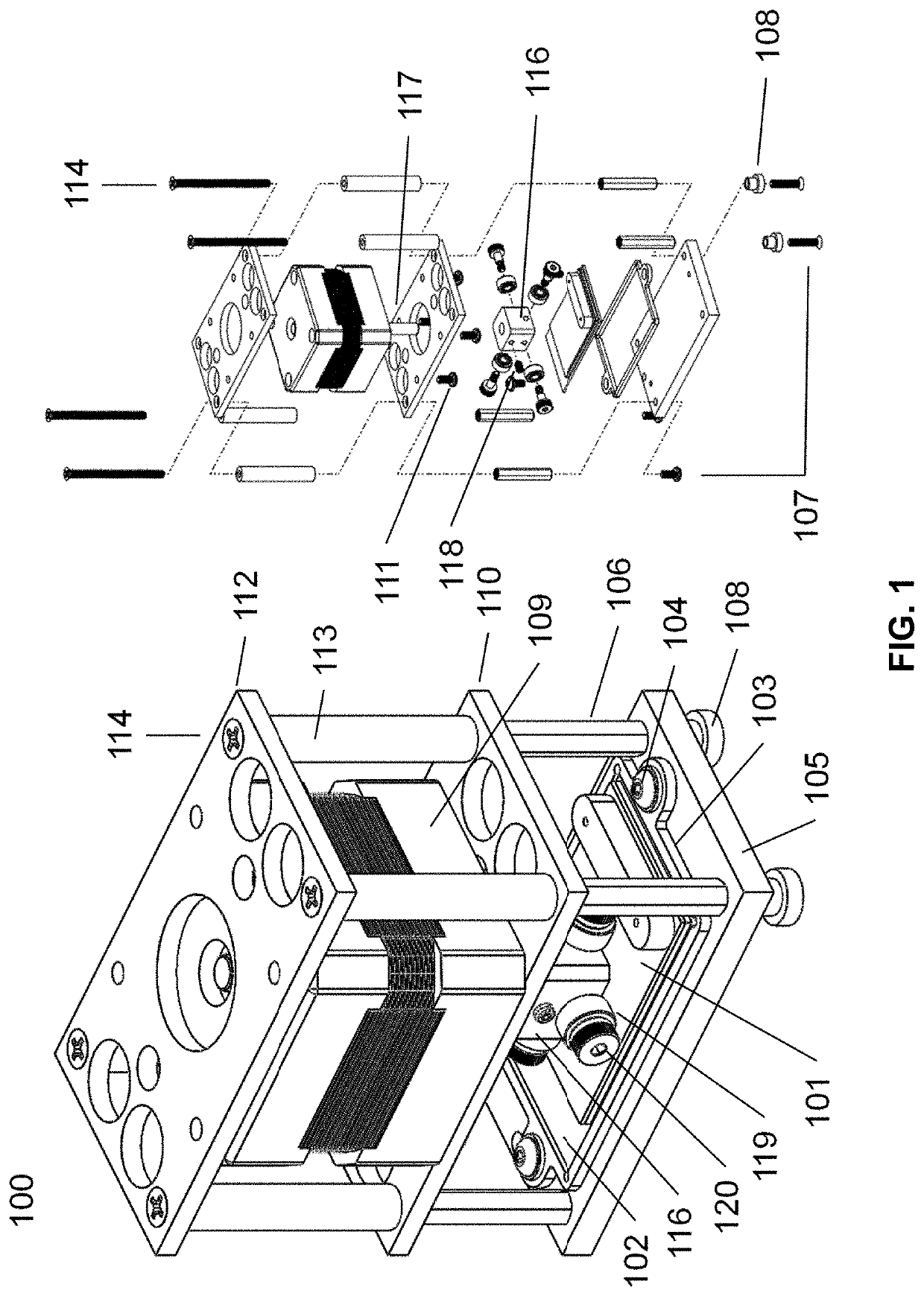
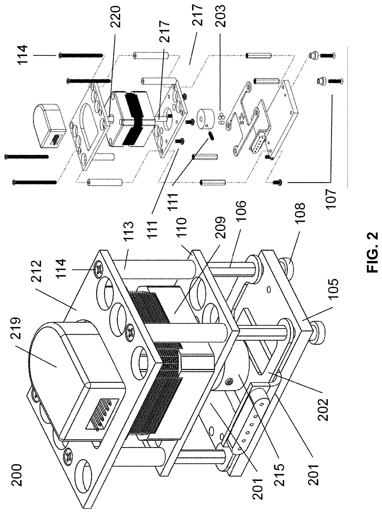
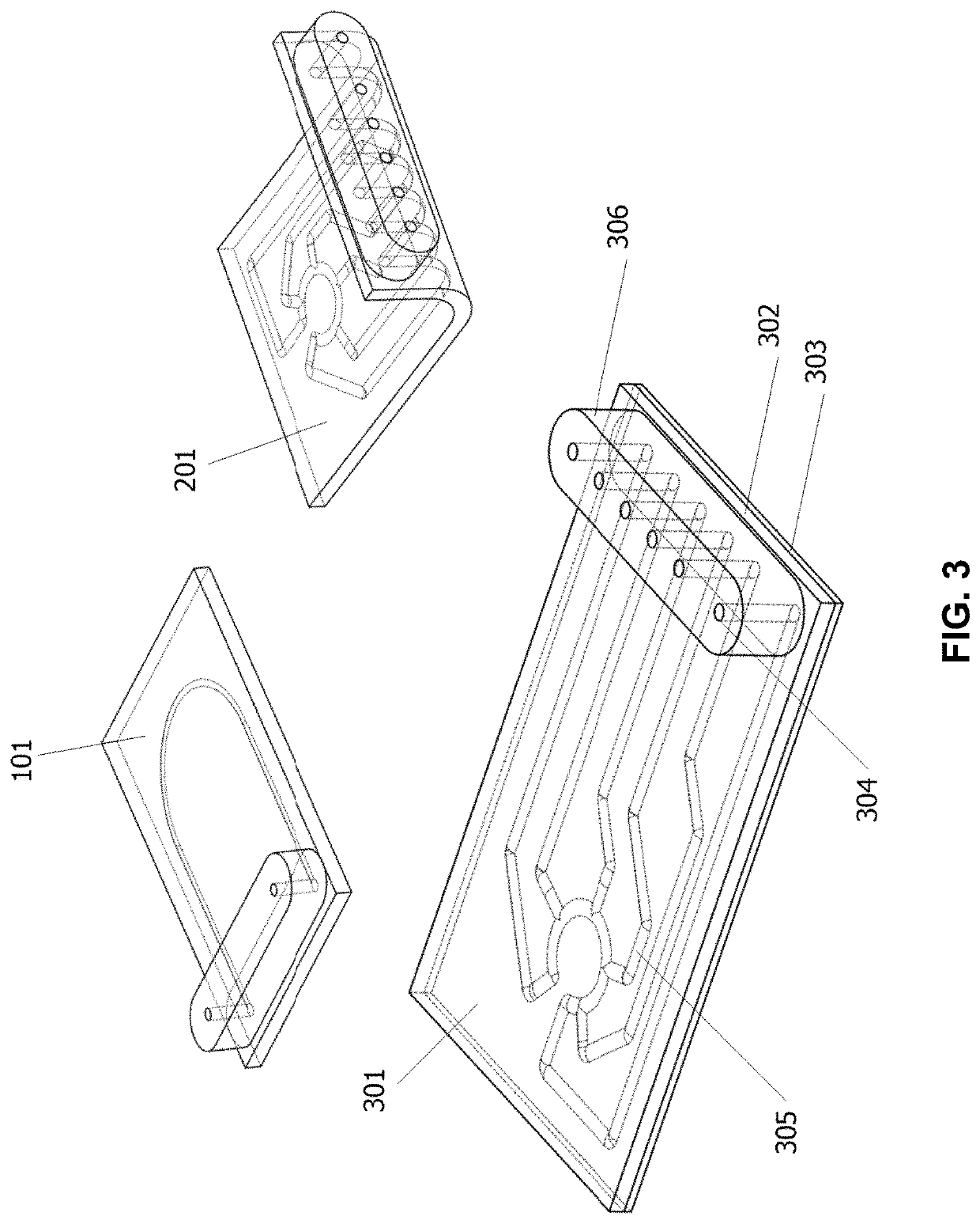
[0099]The invention will now be described more fully hereinafter with reference to the accompanying drawings, in which exemplary embodiments of the invention are shown. The invention may, however, be embodied in many different forms and should not be construed as limited to the embodiments set forth herein. Rather, these embodiments are provided so that this disclosure will be thorough and complete, and will fully convey the scope of the invention to those skilled in the art. Like reference numerals refer to like elements throughout.

[0100]The terms used in this specification generally have their ordinary meanings in the art, within the context of the invention, and in the specific context where each term is used. Certain terms that are used to describe the invention are discussed below, or elsewhere in the specification, to provide additional guidance to the practitioner regarding the description of the invention. For convenience, certain terms may be highlighted, for example using ...


PUM


Abstract

The invention relates to a cartridge of a fluidic device. The fluidic device includes a fluidic chip, a body having a first surface and an opposite, second surface, one or more channels formed in the body in fluidic communications with input ports and output ports for transferring one or more fluids between the input ports and the output ports, and a fluidic chip registration means formed on the first surface for aligning the fluidic chip with a support structure; and an actuator configured to engage with the one or more channels at the second surface of the body for selectively and individually transferring the one or more fluids through the one or more channels from at least one of the input ports to at least one of the output ports at desired flowrates.

Description

CROSS-REFERENCE TO RELATED PATENT APPLICATIONS[0001]This application is a continuation application of International Patent Application No. PCT / US2019 / 047307, filed Aug. 20, 2019, which itself claims priority to and the benefit of U.S. Provisional Patent Application Ser. Nos. 62 / 719,868, and 62 / 868,303, filed Aug. 20, 2018 and Jun. 28, 2019, respectively.[0002]This application is also a continuation-in-part application of U.S. patent application Ser. No. 15 / 820,506, filed Nov. 22, 2017, now allowed, which is a divisional application of U.S. patent application Ser. No. 13 / 877,925, filed Jul. 16, 2013, now abandoned, which is a national stage entry of PCT Application Serial No. PCT / US2011 / 055432, filed Oct. 7, 2011, which claims priority to and the benefit of, U.S. Provisional Patent Application Ser. No. 61 / 390,982, filed Oct. 7, 2010.[0003]This application is also a continuation-in-part application of U.S. patent application Ser. No. 16 / 049,025, filed Jul. 30, 2018, which is a continu...

Claims


Application Information

Patent Timeline
Patent Type & Authority Applications(United States)
IPC IPC(8): B01L3/00
CPCB01L3/502715B01L3/527B01L2400/082B01L3/502746B01L3/502738B01L3/502B01L3/52B01L2200/16B01L2400/0481F04B19/006F04B43/06F04B43/12F04B43/14F16K99/0015F16K99/0057F16K99/0059F16K2099/0084F16K2099/0094
Inventor SCHAFFER, DAVID K.MARKOV, DMITRY A.REISERER, RONALD S.MCCAWLEY, LISAGEUY, MICHAELBRITT, CLAYTON M.WIKSWO, JOHN P.
Owner VANDERBILT UNIV
Why Eureka
Try Eureka