Discharge head for a fluid dispenser and fluid dispenser

a technology of fluid dispenser and discharge head, which is applied in the direction of packaging foodstuffs, instruments, packaged goods, etc., can solve the problems of inability to readily discharge, and achieve the effects of simple assembly, cost-effective configuration, and great structural simplicity

Active Publication Date: 2017-03-02
APTAR RADOLFZELL
View PDF6 Cites 16 Cited by
  • Summary
  • Abstract
  • Description
  • Claims
  • Application Information

AI Technical Summary

Benefits of technology

[0017]This arrangement of the valve component results in great structural simplicity. The valve component is in this case an integral component comprising a resiliently deformable material, such as, for example, an elastomer material. It itself has the discharge opening, for example, in the form of a simple slot or a cross slot. As a result of the deformation of the component as a result of pressure, this discharge opening is opened and the discharge can be produced. In particular as a result of the valve component being fixed between the inner component and the outer component, simple assembly and cost-effective configuration are possible. If the inner component and the outer component are moved relative to each other in accordance with provisions in a translational manner, fixing the valve component to the outer component is advantageous. Thus, the outer component may comprise, for example, two individual members which are pressed together or engaged with each other and between which the peripheral fixing portion of the valve component can be clamped.
[0018]The child-resistance mechanism may have on the inner component and the outer component stop faces which prevent a rotational and / or a translational movement starting from the first relative position and which can be uncoupled from each other by radial displacement of one of the stop faces.
[0019]A relative movement of the inner component and the outer component is accordingly prevented by means of the stop faces which abut each other and which are moved out of engagement with each other when the child-resistance mechanism is moved into the release position. To this end, at least one stop face is preferably radially displaced.

Problems solved by technology

It is already known from the prior art to protect fluid dispensers so that children cannot readily discharge the content.

Method used


Image

  • Discharge head for a fluid dispenser and fluid dispenser
  • Discharge head for a fluid dispenser and fluid dispenser
  • Discharge head for a fluid dispenser and fluid dispenser

Examples


first embodiment

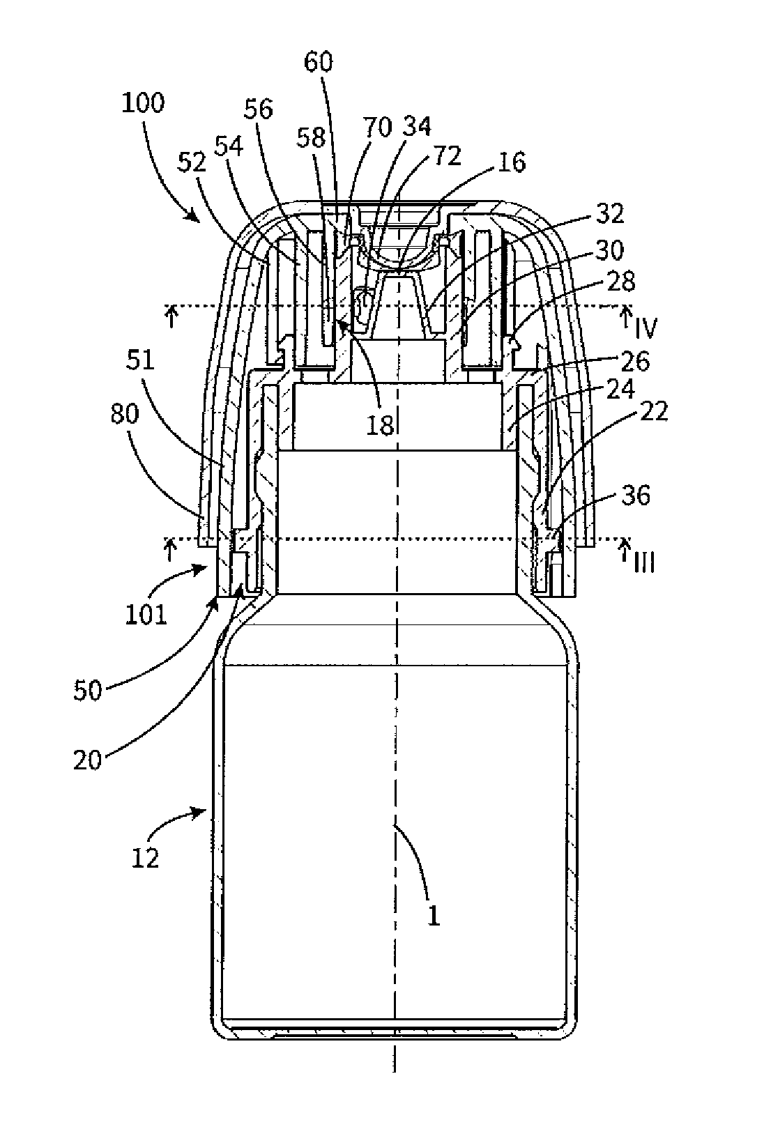
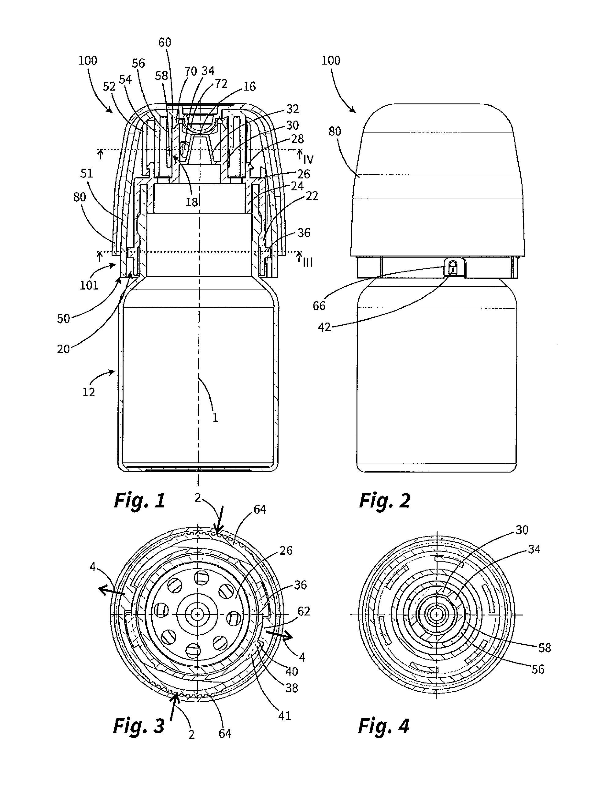
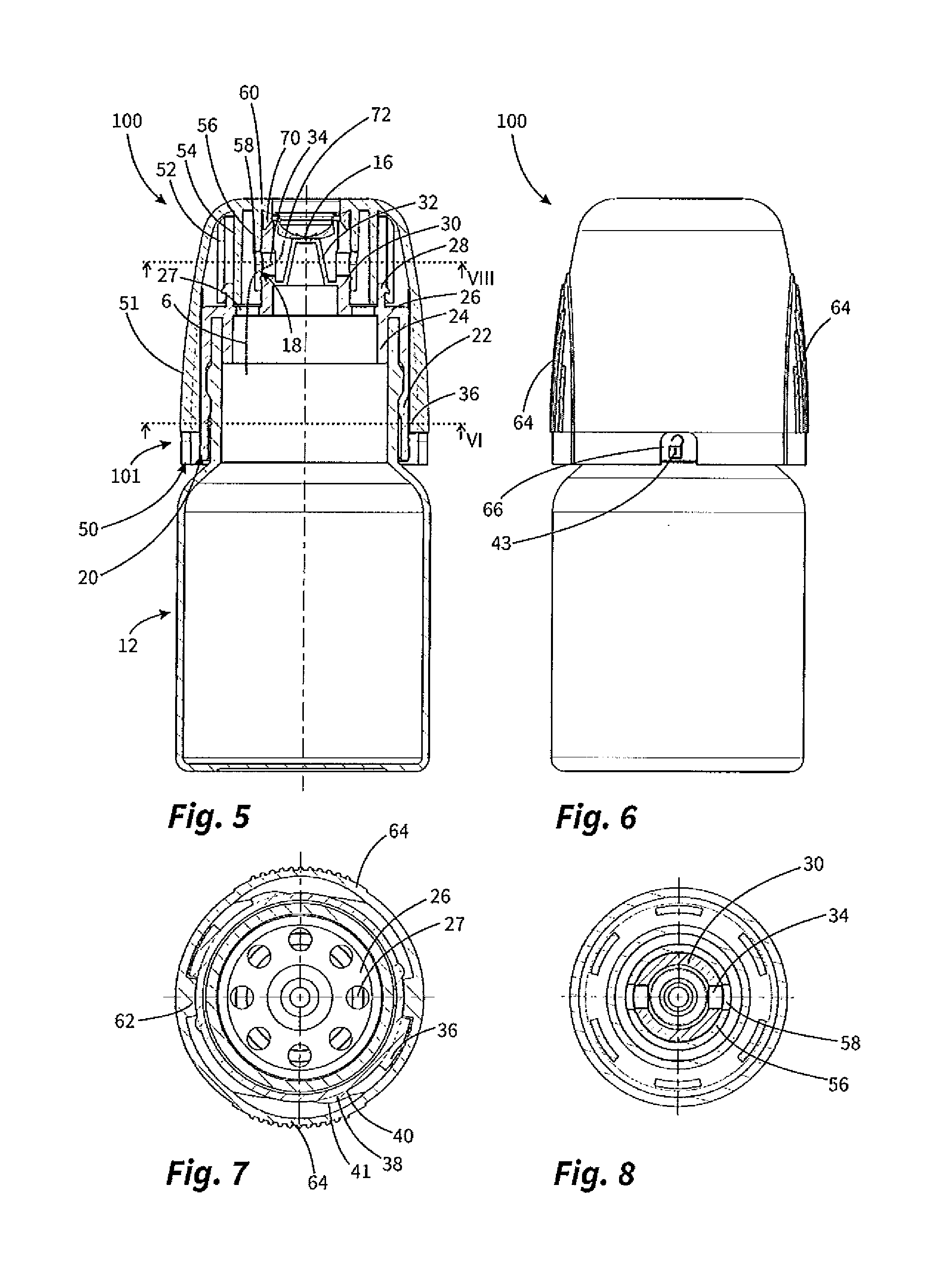
[0055]FIGS. 1 to 8 show a dispenser 100 according to the invention having a discharge head 101 according to the invention. FIGS. 1 to 4 show the state of the dispenser in the locked state and FIGS. 5 to 8 show the state of the dispenser ready for discharge.

[0056]With reference to FIGS. 1 to 4, there can be seen the fluid dispenser 100 which has a bottle-like fluid store 12 which is in the form of a squeezable bottle and which is consequently compressed in accordance with provisions to discharge fluid. In the state of FIGS. 1 to 4, a cap 80 which has in the region of a discharge opening 16 a recess 82, which will be explained in greater detail below, is positioned on the discharge head 101 of the fluid dispenser 100. That cap can also be used as a measuring cup in which the fluid is discharged in accordance with provisions and which preferably has a measurement scale. The cap can further effectively prevent the crystallisation of fluid residues at the other side of the discharge open...

second embodiment

[0065]FIG. 9 shows a dispenser 200 according to the invention with a discharge head 201 according to the invention. Unlike the first fluid dispenser 100, an outlet valve 72 which opens in the event of excess pressure is not provided here. Consequently, a discharge is possible immediately in the inverted position. The chamber above the partition wall 32 consequently itself directly forms the outlet opening 16.

[0066]In the configuration according to FIG. 10, a practically structurally identical fluid dispenser 300 having a practically structurally identical discharge head 301 is again provided. The characteristic feature here is that, instead of the outlet valve 72 opening in the dispenser in the event of excess pressure, there is provided an extraction valve 76. That extraction valve 76 has inherent stability which does not allow any discharge of fluid at all under conventional actuation pressures of the fluid store 12. Instead, it requires an extraction syringe 90 having a tip 92, w...


PUM


Abstract

A discharge head for a fluid container, including a discharge opening and a switching valve which closes and opens a fluid path between the fluid container and the discharge opening. The discharge head has an inner component fixedly connected to a fluid store and an outer component movable relative to the inner component and non-separably connected thereto. The outer component is moved relative to the inner component between a first relative closure position and a second relative open position. The switching valve is opened and closed by movement of the inner component relative to the outer component, is closed in the first position and open in the second position. The inner and outer components are locked in the first position by a child-resistant mechanism, and displacement of the outer component from the first position into the second position is prevented in a locking position of the mechanism.

Description

CROSS-REFERENCE TO RELATED APPLICATIONS[0001]This claims priority from European Patent Application No. 15182116.2, filed on Aug. 24, 2015, the disclosure of which is hereby incorporated by reference in itss entirety into this application.FIELD OF APPLICATION AND PRIOR ART[0002]The invention relates to a discharge head for a fluid dispenser according to the preamble of claim 1. The invention further relates to a fluid dispenser according to the preamble of claim 12.[0003]It is already known from the prior art to protect fluid dispensers so that children cannot readily discharge the content. To this end, for example, it is known to provide fluid dispensers with caps which can be removed only by means of a particular application of force or movement sequences. It is also known to secure actuating handles by means of which a pump of a fluid dispenser can be actuated in order to allow discharge only after a selective release of the securing action. Different child-resistant fluid dispens...

Claims


Application Information

Patent Timeline
Patent Type & Authority Applications(United States)
IPC IPC(8): B65D47/26A61J1/14B65D50/00G01F19/00
CPCB65D47/266B65D50/00A61J1/14G01F19/002B05B11/0005B05B11/007B05B11/0029B05B11/0059B05B11/04B65D47/263B65D47/283B65D50/04B65D47/2031B65D50/046
Inventor GREINER-PERTH, JUERGENMEINEL, PIANADLER, GUENTER
Owner APTAR RADOLFZELL
Why Eureka
Try Eureka