Tool-holder unit of a machine for machining block or slab materials, machine including such unit and method for machining block of slab materials

Active Publication Date: 2021-11-18
GMM SPA
View PDF0 Cites 2 Cited by
  • Summary
  • Abstract
  • Description
  • Claims
  • Application Information

AI Technical Summary

Benefits of technology

[0116]In this way, it is advantageously possible to arrange a suitable number of magnets along a circular crown defined between two inner circumferences of the flanges.
[0117]Moreover, it is advantageously

Problems solved by technology

However, it cannot be excluded that, for various reasons, the tool-holder may be required to withstand higher transversal stresses, even sudden ones, with respect to the rotatio

Method used


Image

  • Tool-holder unit of a machine for machining block or slab materials, machine including such unit and method for machining block of slab materials
  • Tool-holder unit of a machine for machining block or slab materials, machine including such unit and method for machining block of slab materials
  • Tool-holder unit of a machine for machining block or slab materials, machine including such unit and method for machining block of slab materials

Examples


Embodiment Construction

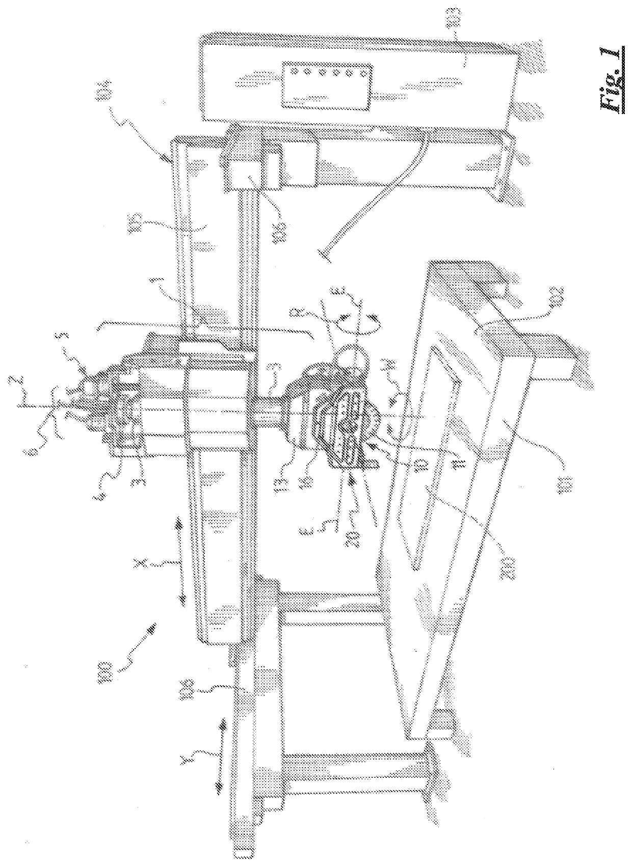
[0168]With initial reference to FIG. 1, a machine for machining block or slab materials, in particular, but not exclusively, stone materials, according to a preferred embodiment of the invention is generally indicated at 100.

[0169]A table 101 is shown defining a working plane 102. The table can be stationary, such as in the illustrated example, or motorised and rotatable about a vertical rotation axis, not shown.

[0170]In general, the table 101 is not part of the machine 100; alternatively, the table 101 can be a component of the machine 100. The block or slab material to be machined is indicated with reference numeral 200.

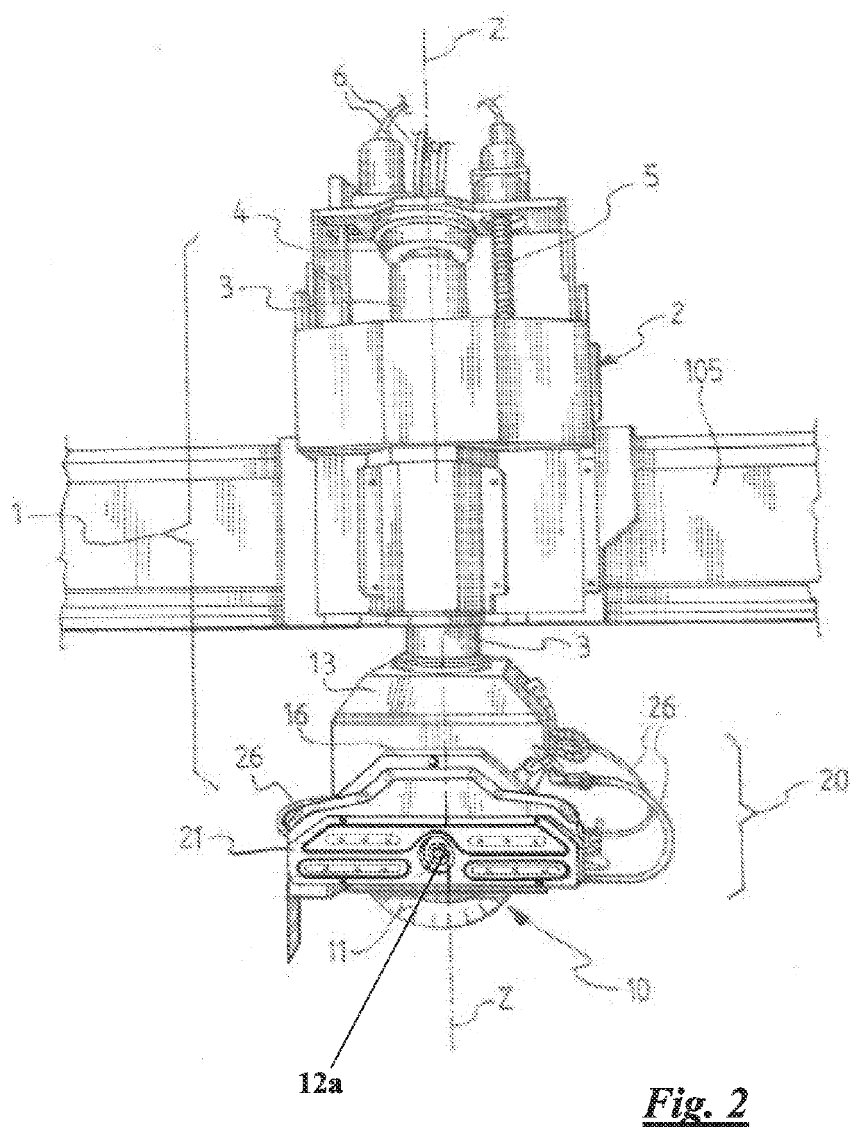
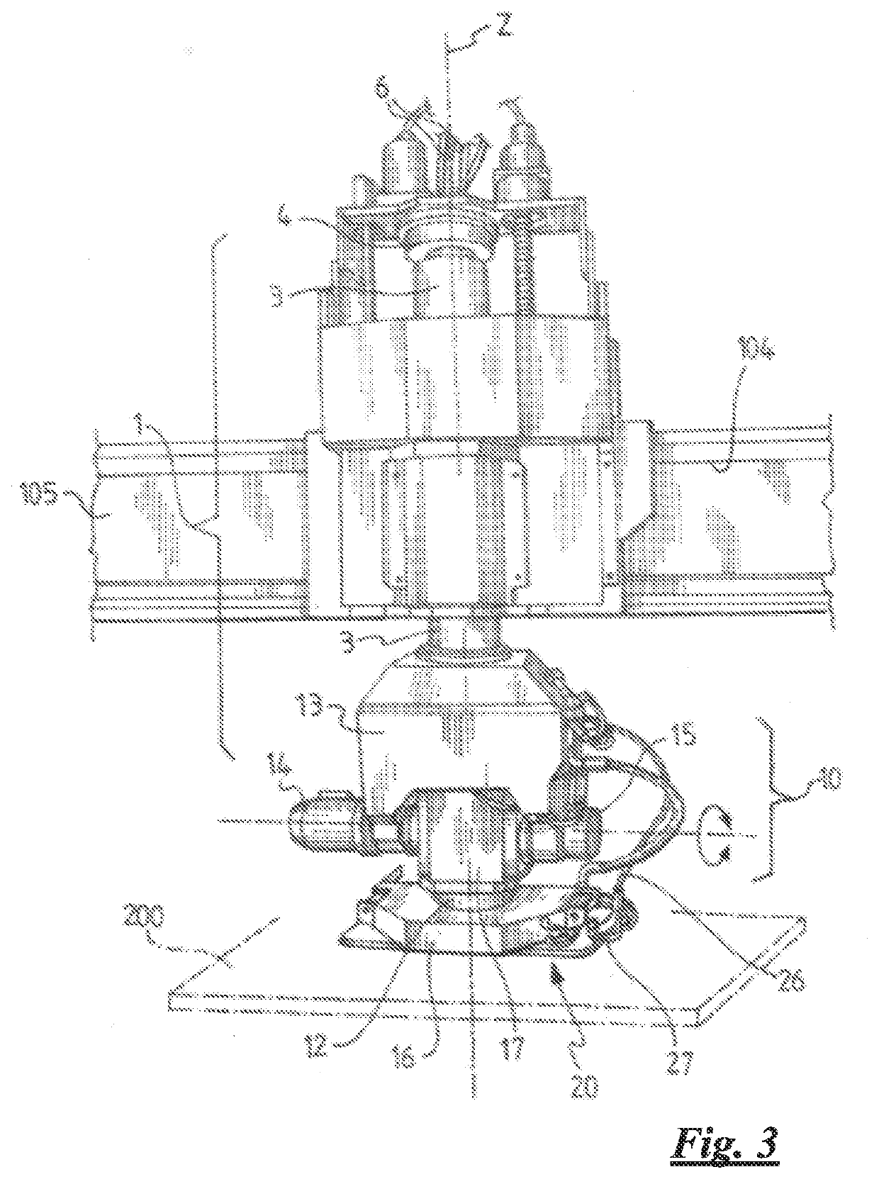
[0171]In this preferred embodiment, the machine 100 comprises a tool-holder unit 10, a corresponding displacing apparatus 1 and a support structure 104.

[0172]The support structure 104 has, in this preferred embodiment, the function of keeping the tool-holder unit 10 and the corresponding displacing apparatus 1 suspended above the working plane 102, on which the mat...


PUM

PropertyMeasurementUnit
Timeaaaaaaaaaa
Elasticityaaaaaaaaaa

Abstract

A tool-holder unit for machining block or slab materials is moveable above a working plane on which the block or slab material is laid. The tool-holder unit includes a spindle with a circular blade and a coupling assembly that couples a second machining tool with the spindle. The tool-unit further includes a tool-holder; a mechanical coupling device configured to rotationally integrate the tool-holder and the spindle; a first axial locking element configured to removably lock the tool-holder on the spindle; a substantially cylindrical shank extending from the tool-holder; a substantially cylindrical housing seat axially positioned in the spindle or a tool-holder coupling element; and a second axial locking element configured to removably lock the tool-holder in the spindle, the axial locking element being configured to removably lock the shank in the respective housing seat.

Description

CROSS REFERENCES[0001]This application is a U.S. National Phase Application of International Application No. PCT / IB / 2019 / 060315 filed on Nov. 29, 2019, which claims priority to Italian Patent Application No. 102018000010747 filed Nov. 30, 2018. The disclosures of International Application No. PCT / IB / 2019 / 060315 and Italian Application No. 102018000010747 are incorporated herein by reference in their entirety.BACKGROUND OF THE INVENTION[0002]The present invention relates to a tool-holder unit of a machine for machining block or slab materials, in particular, but not exclusively, stone materials, such as, for example, marble and granite, or similar materials of a non-natural character. Preferably, these materials are in slab form.[0003]The invention also relates to a machine for machining block or slab materials including such a tool-holder unit and to a method for machining block or slab materials, which method can be implemented by means of such machine. Preferably, these materials ...

Claims


Application Information

Patent Timeline
IPC IPC(8): B23Q3/157B23Q3/12B27B5/32B28D1/04
CPCB23Q3/15713B23Q3/12B28D7/046B28D1/043B27B5/32B23Q1/012
Inventor GUAZZONI, SIMONEGNAPPA, MAURIZIOMEDINA, RICCARDO
Owner GMM SPA
Why Eureka
Try Eureka