
Method for controlling shape measuring apparatus

Active Publication Date: 2021-12-21
MITUTOYO CORP
View PDF15 Cites 1 Cited by
  • Summary
  • Abstract
  • Description
  • Claims
  • Application Information

AI Technical Summary

Benefits of technology

The present invention provides a method for controlling a shape measuring apparatus that improves measurement efficiency by shortening measurement time even if the object being measured has a complicated shape. This is achieved by correcting data about the scanning path and generating corrected scanning path data, as well as correcting the translational velocity pattern to reduce the rotation amount of the rotation command and generate a corrected translational velocity pattern. These corrections help to improve the accuracy and efficiency of the shape measuring process.

Problems solved by technology

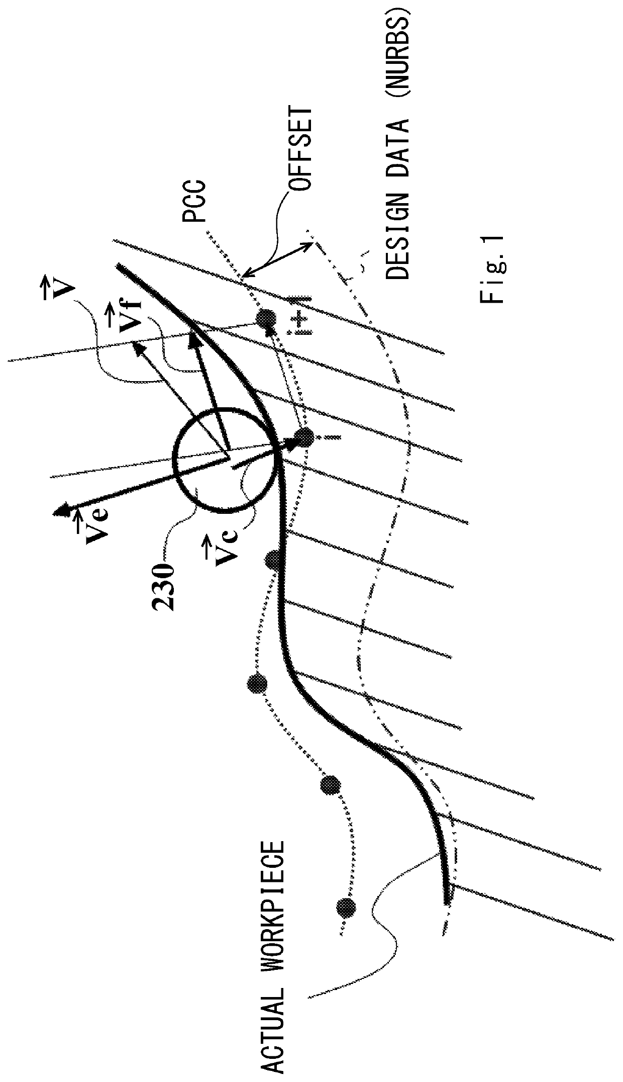
Recently, shapes of objects to be measured have been rather complicated, and performing quick and accurate scanning measurement on workpieces having complicated shapes has been desired.
However, with an existing coordinate measuring machine, as the shape of an object to be measured is complicated, the motion of the probe is complicated accordingly.
Then, the moving speed of the probe becomes slow, and this takes long time to perform measurement.
Furthermore, depending on the shape of a workpiece, the stylus of the probe can interfere with the workpiece, and measurement cannot be performed.

Method used


Image

  • Method for controlling shape measuring apparatus
  • Method for controlling shape measuring apparatus
  • Method for controlling shape measuring apparatus

Examples


first exemplary embodiment

[0119]FIG. 4 is a diagram showing a configuration of an entire shape measuring system 100. The shape measuring system 100 includes a coordinate measuring machine 200, a motion controller 300 that controls the drive of the coordinate measuring machine 200, and a host computer 500 that controls the motion controller 300 and performs necessary data processing.

[0120]The coordinate measuring machine 200 includes a measuring table 210, a translation movement mechanism 220, a probe 230, and a rotary table mechanism 250.

[0121]The translation movement mechanism 220 includes a gate-shaped Y slider 221, an X slider 222, a Z axis column 223, and a Z spindle 224. The Y slider 221 is provided in such a manner as to be slidable on the measuring table 210 in the Y direction. The X slider 222 slides along a beam of the Y slider 221 in the X direction. The Z axis column 223 is fixed to the X slider 222. The Z spindle 224 moves up and down inside the Z axis column 223 in the Z direction.

[0122]On each ...

second exemplary embodiment

[0189]In the first exemplary embodiment, a process of the rotation command generating unit 344 for generating an angular velocity pattern is described.

[0190]Here, the end point of scanning measurement is considered.

[0191]When the tip of the probe 230 (the stylus tip 232) reaches the end point of a set scanning path, the movement of the probe 230 by the translation movement mechanism 220 and the rotation drive of the rotary table 251 are desired to sharply stop.

[0192]A velocity pattern for the translation movement mechanism 220 and the rotary table 251 to decelerate in the last segment to stop at the end point of the scanning path is generated, but the angular velocity cannot be sufficiently decreased in the last segment to be zero at the end point of the scanning path. For this reason, the rotation command generating unit 344 temporally generates an angular velocity pattern for all the segments including the last segment and calculates, if the angular velocity is not sufficiently de...

third exemplary embodiment

[0193]In a third exemplary embodiment, S-shaped acceleration / deceleration processing is described.

[0194]In the first exemplary embodiment, the angular acceleration α is set to a predetermined fixed value, and the angular velocity at an accelerating / decelerating time is a linear function with respect to time. However, it is preferable that the angular velocity gradually accelerates and gradually decelerates in the control of the rotary table. Performing S-shaped acceleration / deceleration processing on a velocity pattern given by a linear function has been disclosed in JP 6050636 B by the applicant (for example, see FIG. 17). With the S-shaped acceleration / deceleration processing, it is possible to smoothly rotate the rotary table and to obtain an angular velocity pattern for smoothly changing a rotating direction as exemplified in FIG. 18 by, for example, blocking the segments Seg4 and Seg5 of the angular velocity pattern shown in FIG. 13 to be connected and then performing the S-sha...


PUM


Abstract

There is provided a method for controlling a shape measuring apparatus that relatively moves a probe and a workpiece with a translation movement mechanism and a rotary drive mechanism to perform scanning measurement on the workpiece by moving the probe along a scanning path set in advance.The method includes setting, by an operator, a scanning path and a rotation angle command for the rotary drive mechanism, dividing data about the scanning path into a plurality of segments and setting a translational velocity pattern of the translation movement mechanism for each segment, calculating for each segment, based on the rotation angle command, a rotation angle value at a start of the segment and a rotation angle value at an end of the segment and generating an angular velocity pattern for each segment, correcting the translational velocity pattern to reduce a rotation amount of the rotation command given by the angular velocity pattern and generating a corrected translational velocity pattern, and driving and controlling, based on a resultant velocity vector based on the corrected translational velocity pattern, the translation movement mechanism and simultaneously driving and controlling, based on an angular velocity command based on the angular velocity pattern, the rotary drive mechanism.

Description

INCORPORATION BY REFERENCE[0001]This application is based upon and claims the benefit of priority from JP patent applications No. 2019-188280 and 2019-188283, filed on Oct. 14, 2019 (DAS code 77BD and F0CD), the disclosures of which are incorporated herein in its entirety by reference.BACKGROUND OF THE INVENTION1. Field of the Invention[0002]The present invention relates to a method for controlling a shape measuring apparatus.2. Description of Related Art[0003]There is a known shape measuring apparatus that measures the shape of an object to be measured by moving a stylus tip along a surface of the object to be measured while scanning the surface (for example, see JP 5274782 B, JP 6030339 B, and JP 6063161 B). In order to perform scanning measurement, a path for the scanning measurement needs to be set.[0004]The apparatus disclosed in JP 5274782 B converts design data about a scanning path based on CAD data or the like (for example, non-uniform rational B-spline (NURBS) data) into a...

Claims


Application Information

Patent Timeline
IPC IPC(8): G01B5/008G01B11/02G01B11/25G01B21/04G05B19/401G05B19/19
CPCG01B11/02G01B5/008G01B11/254G01B11/2518G01B21/04G05B19/19G05B19/401G01B21/00G01B21/20G01B7/008G01B7/28G01B11/005G01B11/24G01B5/0004G05B19/4163G01B5/205
Inventor SAKAKIBARA, SHOTAKAMITANI, HIROSHI
Owner MITUTOYO CORP
Learn More