Wave-energized diode pump
a diode pump and wave-energized technology, applied in the direction of mechanical equipment, machines/engines, sea energy generation, etc., can solve the problem of inclination about a vertical axis, and achieve the effect of efficient harvesting
- Summary
- Abstract
- Description
- Claims
- Application Information
AI Technical Summary
Benefits of technology
Problems solved by technology
Method used
Image

Examples
embodiment 650
[0500]FIG. 71 shows a perspective side view of an embodiment 650 of the present disclosure that incorporates a plurality of the type of power takeoff (PTO) disclosed herein. The embodiment floats adjacent to an upper surface 651 of a body of water over which waves tend to pass. Each hexagonal columnar structure, e.g., 652-654, is a PTO of one of the types disclosed herein. The embodiment may incorporate a variety of different PTOs, PTOs of different sizes, PTOs of different rated electrical power levels, PTOs fabricated of different materials, PTOs converting the energy of waves into electrical power by means of different operating fluids, PTOs which draw water from the body of water 651 and PTOs that recycle an operating fluid within a closed system.
[0501]The illustrated multi-PTO embodiment 650 incorporates an energy-consuming processing module 655, system, factory, mechanism, and / or device, and therein or therethrough utilizes at least a portion of the electrical power that it pr...
embodiment 700
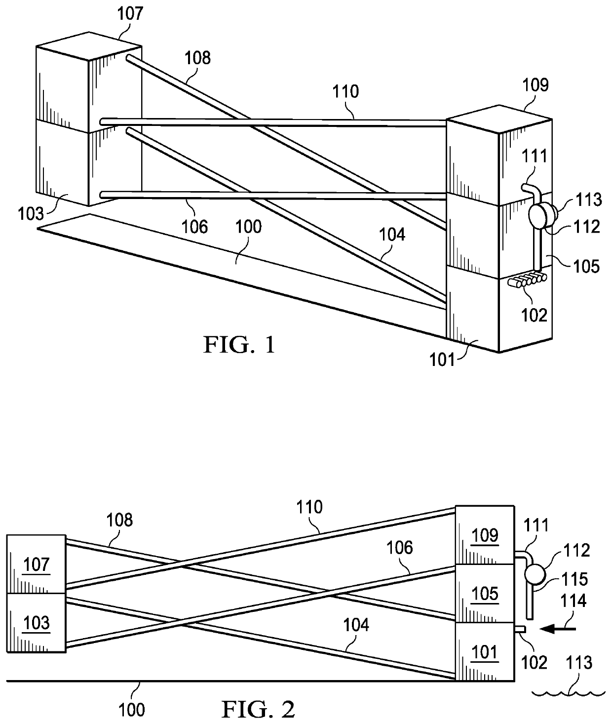
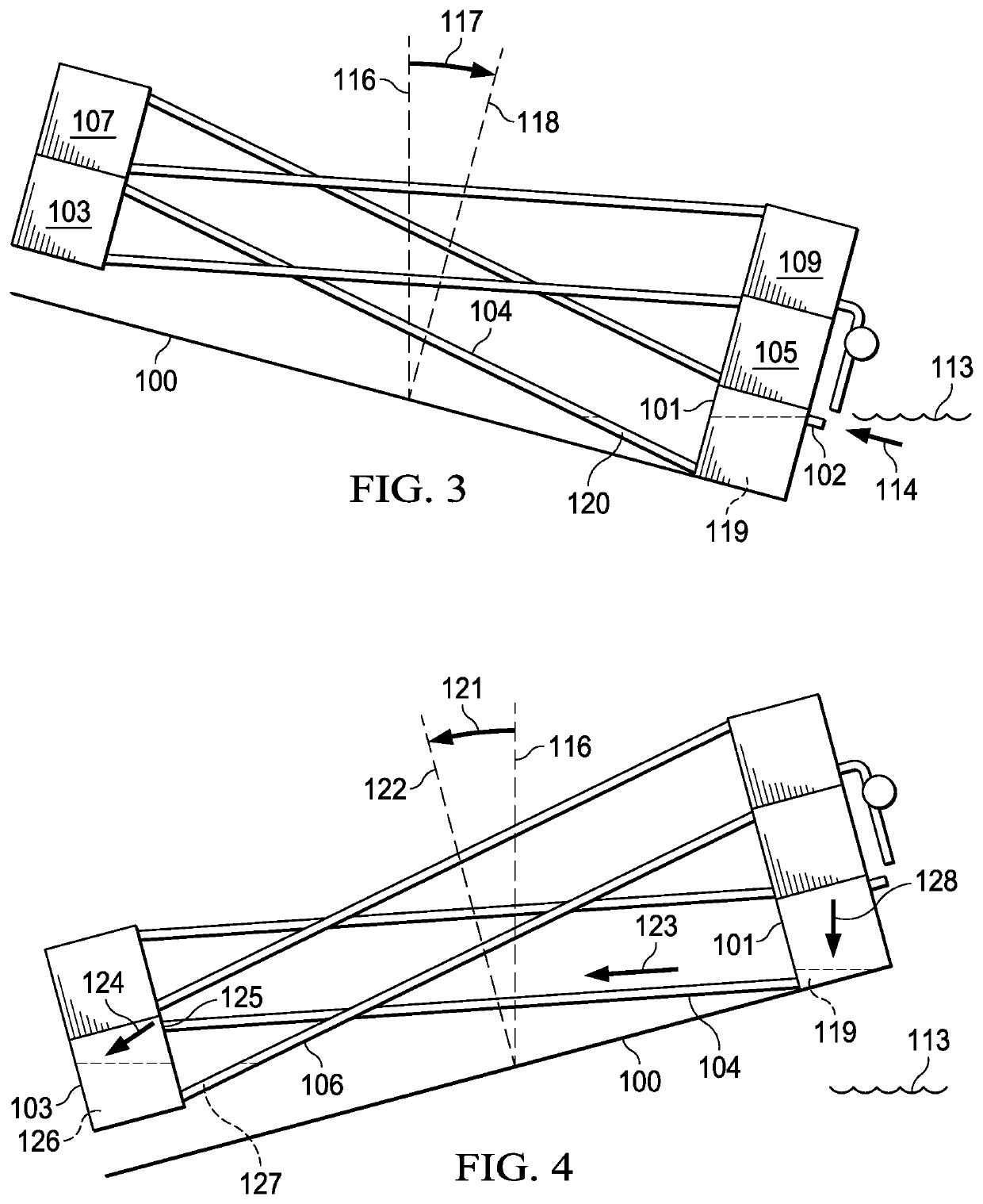
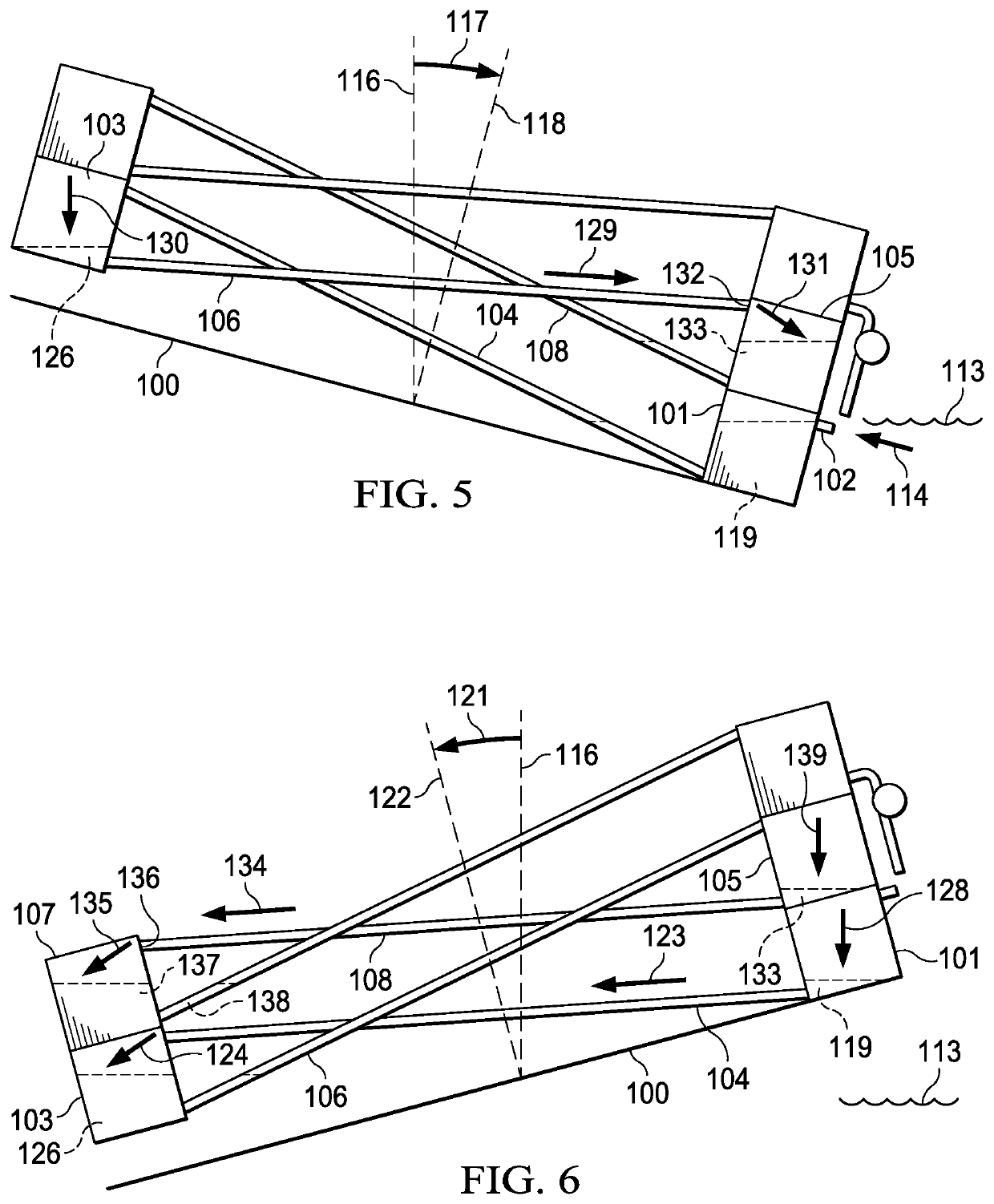
[0509]FIG. 72 shows a perspective side view of an embodiment 700 of the present disclosure. A compartment, enclosure, and / or chamber 701, contains a wave-energized diode pump similar to the one illustrated in FIGS. 15-19 which utilizes reservoirs connected to ramps, and / or inclined channels, over and / or through which, in response to wave-induced tilting of the diode pump, water flows back and forth between opposing reservoirs at ever increasing relative heights thereby progressively and / or incrementally gaining gravitational potential energy.
[0510]Water that has flowed through the diode pump and reached the top of the pump is thereafter directed into a channel (not visible) containing a water turbine (not visible) rotatably connected to a generator 702. The water flowing down through the turbine channel engages and / or energizes the water turbine thereby imparting rotational kinetic energy and / or rotational torque to the generator 702 and thereby generating electrical power.
[0511]The...
embodiment 800
[0559]FIG. 87 shows a perspective side view of an embodiment 800 of the present disclosure. The illustrated embodiment is similar to an “autonomous underwater vehicle” (AUV) and is capable of cruising through a body of water below its surface. However, in FIG. 87 the embodiment is shown floating adjacent to an upper surface 801 of a body of water over which waves are passing. The embodiment incorporates, includes, and / or utilizes, four stabilizing and / or directional fins, e.g., 802, at a fore 803, forward, leading, and / or upper end, as well as four stabilizing and / or directional fins, e.g., 804, at an aft 805, stern, trailing, and / or lower end. In combination with a forward or backward thrust, the embodiment's fins, e.g., 802 and 804, enable and / or permit the embodiment to alter, adjust, control, regulate, change, and / or modify, its pitch, yaw, roll, course, direction, and / or movements.
[0560]The illustrated embodiment 800 has a hull, shape, form, and / or displacement, that is primari...
PUM
 Abstract
Description
Claims
Application Information
 - R&D
- Intellectual Property
- Life Sciences
- Materials
- Tech Scout
- Unparalleled Data Quality
- Higher Quality Content
- 60% Fewer Hallucinations
Browse by: Latest US Patents, China's latest patents, Technical Efficacy Thesaurus, Application Domain, Technology Topic, Popular Technical Reports.
© 2025 PatSnap. All rights reserved.Legal|Privacy policy|Modern Slavery Act Transparency Statement|Sitemap|About US| Contact US: help@patsnap.com