

Autonomous driving module mounting structure
a technology for autonomous driving modules and mounting structures, which is applied in the direction of vehicle components, electrical/fluid circuits, electrical apparatus casings/cabinets/drawers, etc., can solve the problems of difficult opening and closing the sunroof and the unlikely damage of the autonomous driving modul
- Summary
- Abstract
- Description
- Claims
- Application Information
AI Technical Summary
Benefits of technology
Problems solved by technology
Method used
Image

Examples
first embodiment
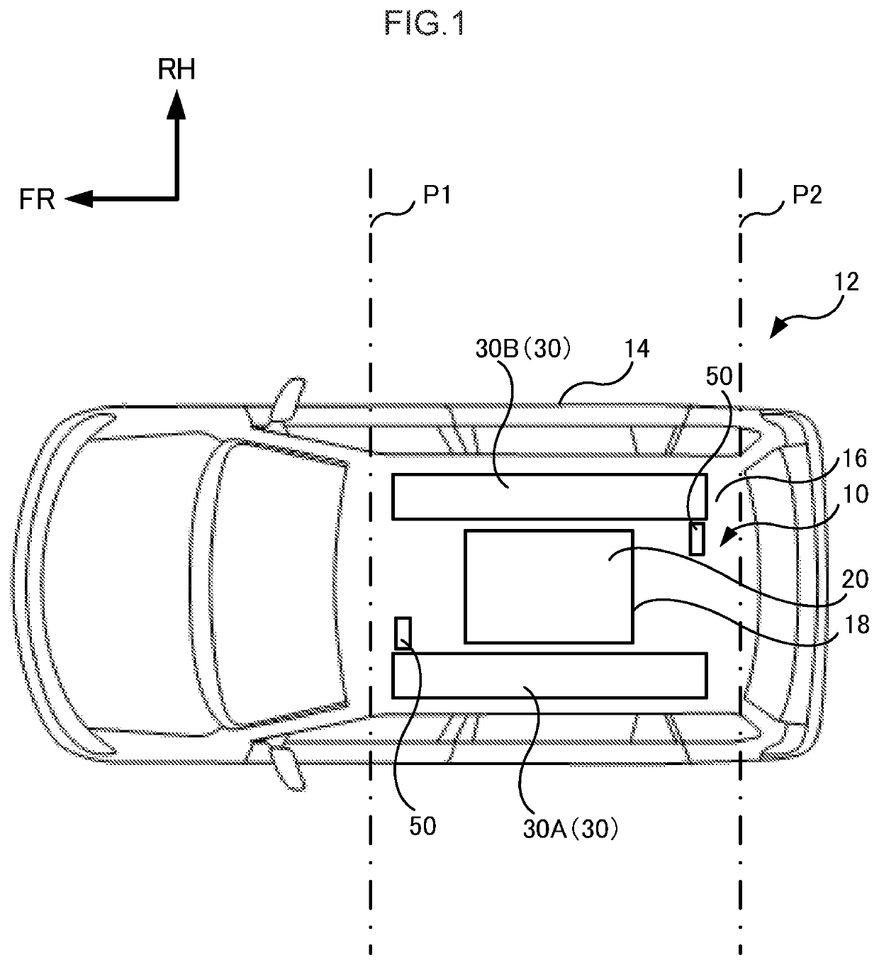
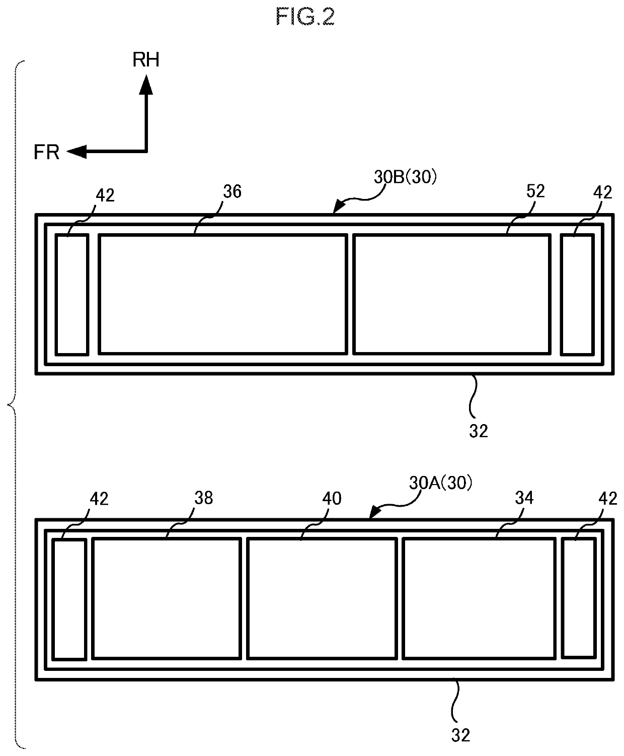
[0039]An autonomous driving module mounting structure 10 of a first embodiment pertaining to the disclosure will be described. First, the overall configuration of a vehicle 12 serving as an autonomous driving battery electric vehicle to which the autonomous driving module mounting structure 10 is applied will be described using FIG. 1 to FIG. 7. It will be noted that arrow FR appropriately shown in the drawings indicates the vehicle forward direction, arrow UP indicates the vehicle upward direction, and arrow RH indicates the rightward direction in the vehicle width direction. Furthermore, in the drawings, the sizes and shapes of a sunroof and module cases sometimes differ from their actual dimensions for convenience of description. In the following embodiment, the vehicle 12 is a minivan as an example, but the autonomous driving module mounting structure 10 can be applied to all types of vehicles so long as they are vehicles to which a sunroof can be mounted, such as ordinary passe...
second embodiment
[0067]An autonomous driving module mounting structure 10A of a second embodiment pertaining to the disclosure will be described. FIG. 8 is a top view of the vehicle 12 to which the autonomous driving module mounting structure 10A is applied.
[0068]As shown in FIG. 8, the autonomous driving module mounting structure 10A of the second embodiment includes one autonomous driving module 30C. The autonomous driving module 30C is configured as a result of plural devices being housed inside a module case 32A serving as an outer shell. The module case 32A has the shape of a hollow cuboid whose lengthwise direction coincides with the vehicle front-rear direction, and has an opening 70 in its central portion. That is, the autonomous driving module 30C is disposed along the vehicle front-rear direction at both sides in the vehicle width direction of the open portion 18 in top view and along the vehicle width direction at both sides in the vehicle front-rear direction of the open portion 18 in to...
third embodiment
[0073]Next, an autonomous driving module mounting structure 10B of a third embodiment pertaining to the disclosure will be described. FIG. 9 is a top view of the vehicle 12 to which the autonomous driving module mounting structure 10B is applied.
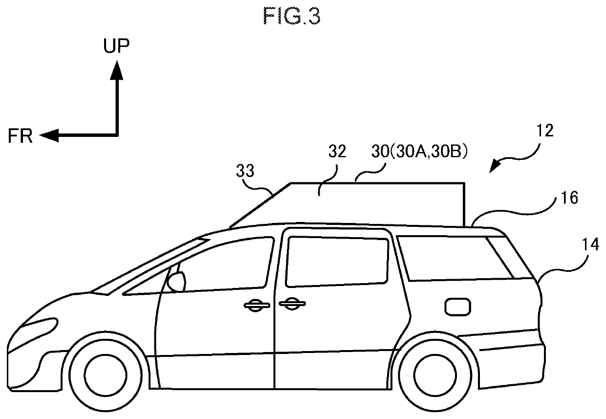
[0074]As shown in FIG. 9, the autonomous driving module mounting structure 10B of the third embodiment includes one autonomous driving module 30D. The autonomous driving module 30D is configured as a result of plural devices being housed inside a module case 32B serving as an outer shell. The module case 32B is thick in the vehicle up and down direction and has the shape of a sideways “U” that is open in the vehicle rearward direction. The module case 32B has, as in the first embodiment, a sloping portion 33 that descends from the vehicle rear side to the vehicle front side in side view (see FIG. 3). Furthermore, although this is not shown in the drawing, the upper surface of the outer section of the roof panel 16 is, as in the first embodim...
PUM
 Abstract
Description
Claims
Application Information