Mobility management system in personal communication system

a technology of personal communication and management system, applied in direction finders using radio waves, wireless communication services, instruments, etc., can solve the problems of congested communication channels of the network, affecting the service life of users, and requiring a lot of time and money for each subscriber

Inactive Publication Date: 2000-01-25
NEC CORP
View PDF10 Cites 49 Cited by
  • Summary
  • Abstract
  • Description
  • Claims
  • Application Information

AI Technical Summary

Problems solved by technology

Consequently, when the detaching method is used, the number of signals that are transmitted between subscriber terminal units and the mobile communication network increases, thereby congesting the communication channels of the network.
Thus, each subscriber has to spend a lot of time and money.
Thus, the number of signals that are transmitted between each subscriber terminal unit and the mobile communication network increases, thereby congesting the communication channels of the network.
Moreover, in a conventional location tracking system, while each subscriber is traveling, accurate tracking information cannot be obtained.
In other words, there are wasteful call ins.
Since tracking information of such subscribers has much changed information, the number of signals that are transmitted between each subscriber terminal and the mobile communication network increases, thereby congesting the communication channels of the network.

Method used


Image

  • Mobility management system in personal communication system
  • Mobility management system in personal communication system
  • Mobility management system in personal communication system

Examples


first embodiment

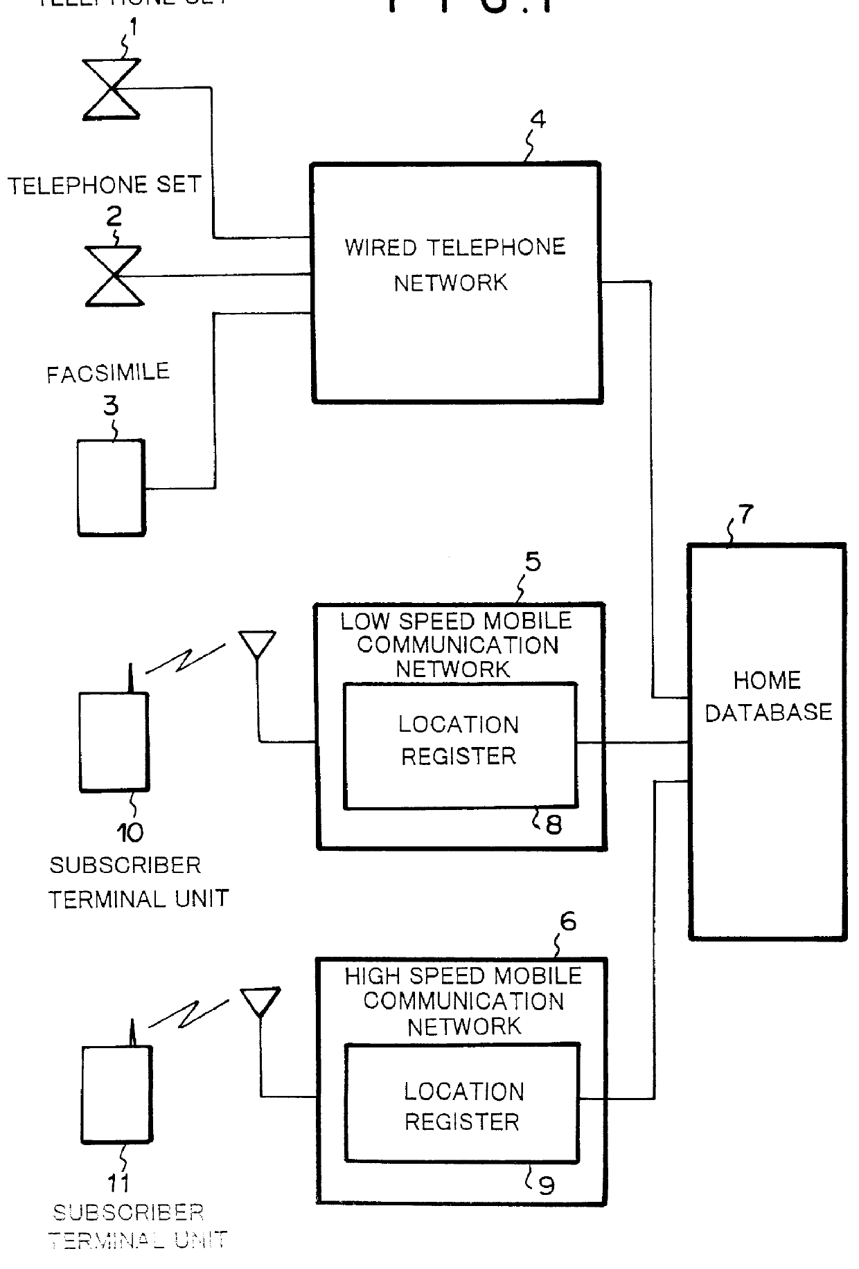
FIG. 1 is a schematic diagram showing the structure of a mobility management system in a personal communication system according to the present invention. The mobility management system in the personal communication system shown in FIG. 1 comprises wired telephone network 4, low speed mobile communication network 5, high speed mobile communication network 6, and home database 7. Wired telephone network 4 accommodates telephone set 1, telephone set 2, and facsimile machine 3. Telephone set 1 is used in the home of a subscriber. Telephone set 2 is used in the company of the subscriber. Facsimile machine 3 is used in the company of the subscriber. Wired telephone network 4 manages an updating operation of a registered location of a terminal unit corresponding to a location registration update request signal that is sent from the terminal unit to inform that the subscriber uses the terminal unit. Low speed mobile communication network 5 is connected to low speed mobile communication sub...

second embodiment

FIG. 10 is a schematic diagram showing the structure of a mobility management system in a personal communication system according to the present invention. Referring to FIG. 10, the mobility management system comprises wired telephone network 34, low speed mobile communication network 35, high speed mobile communication network 36, and center home database 37. Wired telephone network 34 accommodates telephone set 31 used in the home of subscriber A, telephone set 32 used in the company of subscriber A, and a facsimile 33 used in the company of subscriber A. Wired telephone network 34 has distributed home database (DHDB) 38a. Low speed mobile communication network 35 accommodates low speed mobile communication subscriber terminal unit 40 that is a terminal unit equivalent to a PHS telephone set. Low speed mobile communication network 35 has distributed home database 38b. High speed mobile communication network 36 accommodates high speed mobile communication subscriber terminal unit 4...


PUM


Abstract

A subscriber normally uses telephone sets 1 and 2 and a facsimile machine 3 accommodated in a wired telephone network 4, a subscriber terminal unit 10 that is a handy phone accommodated in a low speed mobile communication network 5, and a subscriber terminal unit 11 that is a portable telephone set accommodated in a high speed mobile communication network 6. Each of the networks is connected to a home database 7 to which the subscriber has subscribed. The home database 7 shares mobility management information for tracking a subscriber to which a call is connected in the wired communication system and mobility management information for registering the location of the subscriber who travels in the mobile communication system. The home database 7 updates the mobility management information for tracking the location of the subscriber with a location registration update request signal issued by the subscriber and changes the subscriber tracking priority.

Description

1. Field of the InventionThe present invention relates to a mobility management system in a personal communication system and in particular, a mobility management system in a personal communication system in which the mobility of a communication terminal unit in the field of the personal communication is considered.2. Description of the Prior ArtAs an example of a mobility management system in a conventional personal communication system, a location updating system that updates the content of a location register upon traveling of a subscriber terminal unit among location registered areas is known. Next, a conventional location Ail updating system will be explained. FIG. 14 is a schematic diagram showing the structure of a network of a conventional location updating system. There are various mobile communication systems that have been structured by different communication companies. In each mobile communication system, the service area thereof is subdivided into several sub-areas. Th...

Claims


Application Information

Patent Timeline
Patent Type & Authority Patents(United States)
IPC IPC(8): H04Q7/38H04Q3/00H04Q7/24H04M3/54H04W8/04H04W8/12H04W8/18H04W8/20H04W60/04H04W76/04H04W92/02
CPCH04Q3/005H04W8/04H04W8/12H04W8/18H04W8/20H04W60/04H04W76/04H04W92/02H04W76/20
Inventor TANAKA, SHOJI
Owner NEC CORP
Why Eureka
Try Eureka