Method for controlling an optic disk

a technology of optic disks and optical disks, applied in the field of optic disks, can solve the problems of consuming available memory space and longer execution time of the update process

Inactive Publication Date: 2001-01-02
MEDIATEK INC
View PDF5 Cites 63 Cited by
  • Summary
  • Abstract
  • Description
  • Claims
  • Application Information

AI Technical Summary

Benefits of technology

It is another an objective of the present invention to provide a method for updating a firmware information so as to reduce an updating time.
In accordance with the foregoing CD-ROM chip and other objectives of the present invention, a method to address the extra memory is provided. In this method, when firmware information is updated, the firmware information and execution commands are divided into several parts. Each part is stored in a different memory area. For example, the firmware information is written into the ROM through the buffer memory, and the execution commands are stored in the extra memory. Therefore, the firmware information and the execution commands have their own individual memories. The firmware information can be updated in a faster speed.
Moreover, in the invention, a refresh queue unit is also introduced. The refresh queue provides a larger refreshing buffer capability so that a refreshing sequence is not delayed during the memories are busy in update actions.

Problems solved by technology

This manner consumes the available memory space of the ROM and further causes a longer execution time of the update process.

Method used


Image

  • Method for controlling an optic disk
  • Method for controlling an optic disk
  • Method for controlling an optic disk

Examples


Embodiment Construction

As mention in the previous descriptions, CD-ROM apparatus is an essential periphery apparatus in computer industry. In order to obtain a faster performance to match the main computer performance, the CD-ROM needs a faster updating method to update firmware information. In the invention, a more efficient updating method is introduced to be able to update firmware of CD-ROM system in a faster speed. The purpose of the invention is achieved by also including a CD-ROM chip. The method is also very suitable for any current CD-ROM system so that the method of the invention can be easily applied.

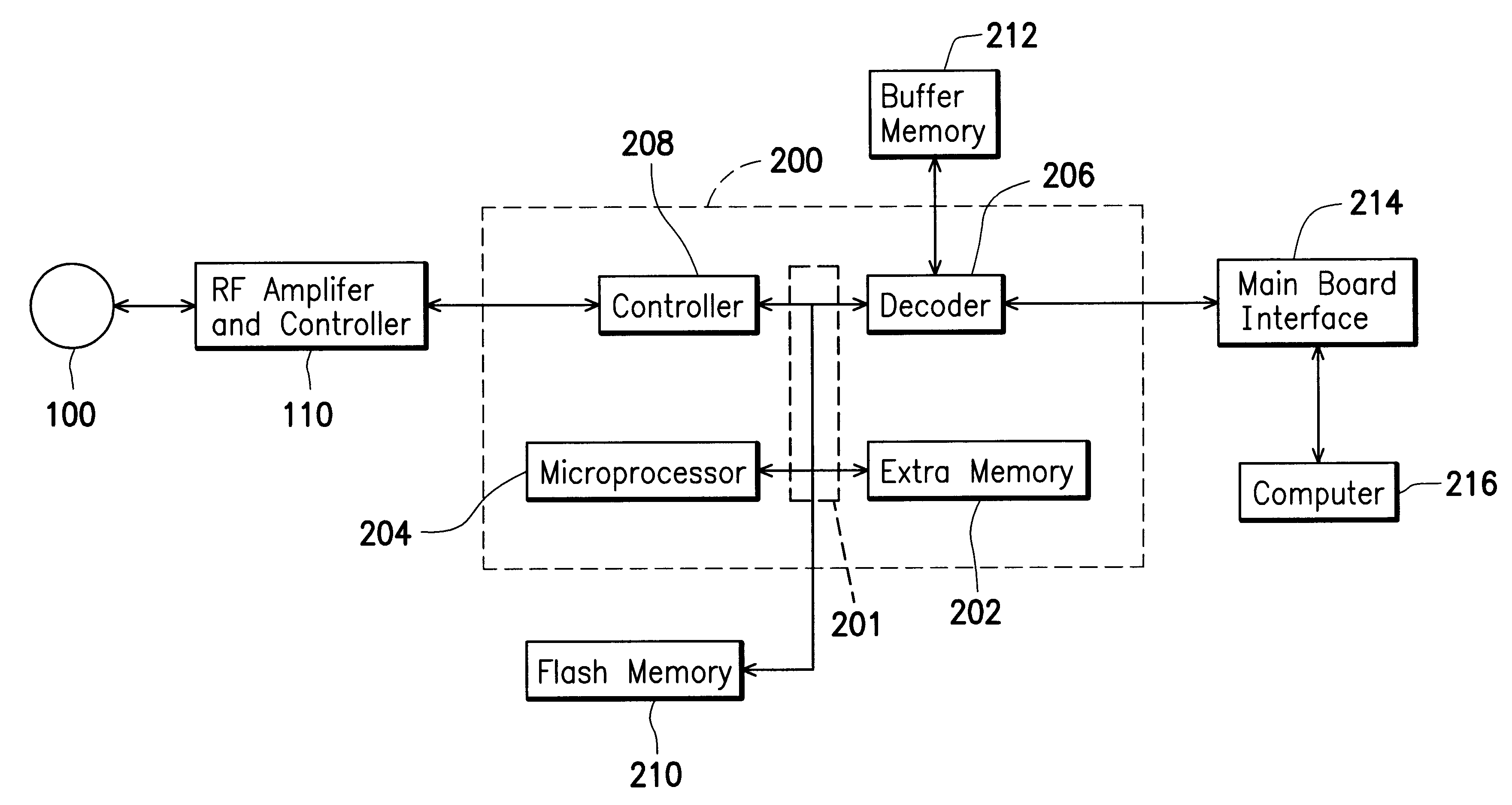
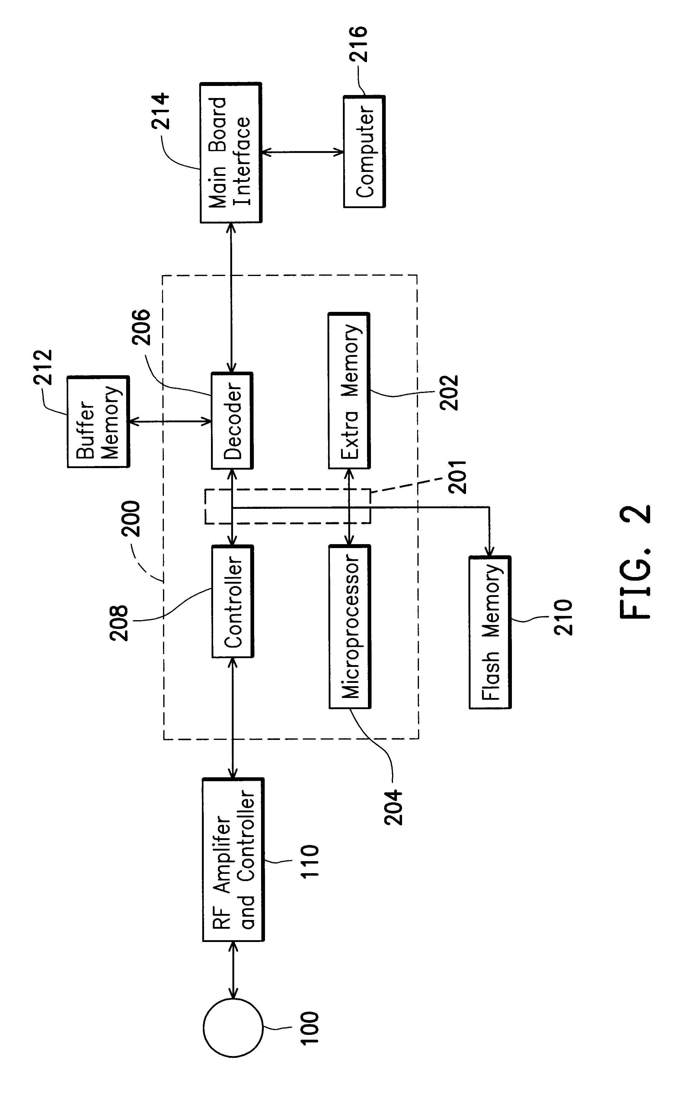
FIG. 2 is a block diagram, schematically illustrating a CD-ROM system including a system control chip and its periphery units, according to a preferred embodiment of the invention. In FIG. 2, a CD-ROM system control chip 200 is used to update firmware information, which is stored in a memory 210, such as a flash memory 210 or an electrical erasable programmable ROM (EEPROM). The system control chip...


PUM


Abstract

A CD-ROM control chip is provided for a use of firmware information update in the CD-ROM system. The control chip at least includes a microprocessor, a decoder, a controller, and an extra memory. The microprocessor is coupled to a data bus, and further coupled to an external ROM, which stores all firmware information. The decoder is coupled to the microprocessor through the data bus, and is also coupled to an external buffer memory and an external main board interface. The external main board interface allows the CD-ROM control chip to communicate with an external computer. The controller is coupled to the decoder, and is coupled to the microprocessor the data bus. The controller is used to receive information and control signals from an external CD. The extra memory is coupled to the microprocessor through the data bus. When the microprocessor starts to update the firmware information, it generates at least one output enabling signal, one chip selecting signal, and one writing-in signal, and sends these signals to the external ROM. The external ROM is treated as an information storing space, and the extra memory is treated as execution space used by an update program routine.

Description

1. Field of the InventionThis invention relates to an optic disk, and more particularly to a control method used to control an optic disk system.2. Description of Related ArtFIG. 1 is a schematic drawing of an optic disk system of a conventional compactdisk (CD) read-only-memory (ROM), or called CD-ROM. In FIG. 1, a CD 100 includes a large amount of data, which are to read by an optic pickup head 102. When data are processed by a radio-frequency (RF) amplifier and controller 110, the processed data are decoded by a decoder 114. The decoded data are stored in a buffer memory 116. A microprocessor 112 is used to control the RF amplifier and controller 110, the decoder 114, the optic pickup head, and a driving force to drive the optic disk 100 to obtain a proper performance. In other words, the microprocessor 112 controls all operations of an optic disk system, such as a CD-ROM system. The microprocessor 112 is also coupled to a ROM 118, which stores all needed data, commands, instruct...

Claims


Application Information

Patent Timeline
Patent Type & Authority Patents(United States)
IPC IPC(8): G06F9/445
CPCG06F8/65
Inventor HU, YI-KWANG
Owner MEDIATEK INC
Why Eureka
Try Eureka