Encoding method and apparatus and recording medium

a technology applied in the field of encoding method and recording medium, can solve the problems of obstructing the reduction in the size of reproducing means, unable to achieve psychoacoustic optimal actual noise feeling, and unable to achieve optimal results

Inactive Publication Date: 2002-03-12
SONY CORP +1
View PDF6 Cites 52 Cited by
  • Summary
  • Abstract
  • Description
  • Claims
  • Application Information

AI Technical Summary

Problems solved by technology

However, if the transform block length for transform is lengthened, more work area is required for transform, thus obstructing reduction in size of reproducing means.
However, the actual noise feeling is not psychoacoustically optimum because the psychoacoustic masking effect is not exploited.
However, if this technique is used to measure characteristics of a sine wave input, non-optimum results are obtained because of the fixed allocation of bits among the critical bands.
Since the relation between the normalization coefficient information and the quantization fineness information is set at the time of setting the standard, it becomes impossible to introduce the quantization fineness control based on a more advanced psychoacoustic model in future.
Meanwhile, if it is desired to attempt standard expansion using a signal decoding method which enables a larger number of channel signals to be reproduced by st...

Method used


Image

  • Encoding method and apparatus and recording medium
  • Encoding method and apparatus and recording medium
  • Encoding method and apparatus and recording medium

Examples


Embodiment Construction

Referring to the drawings, preferred embodiments of the present invention will be explained in detail.

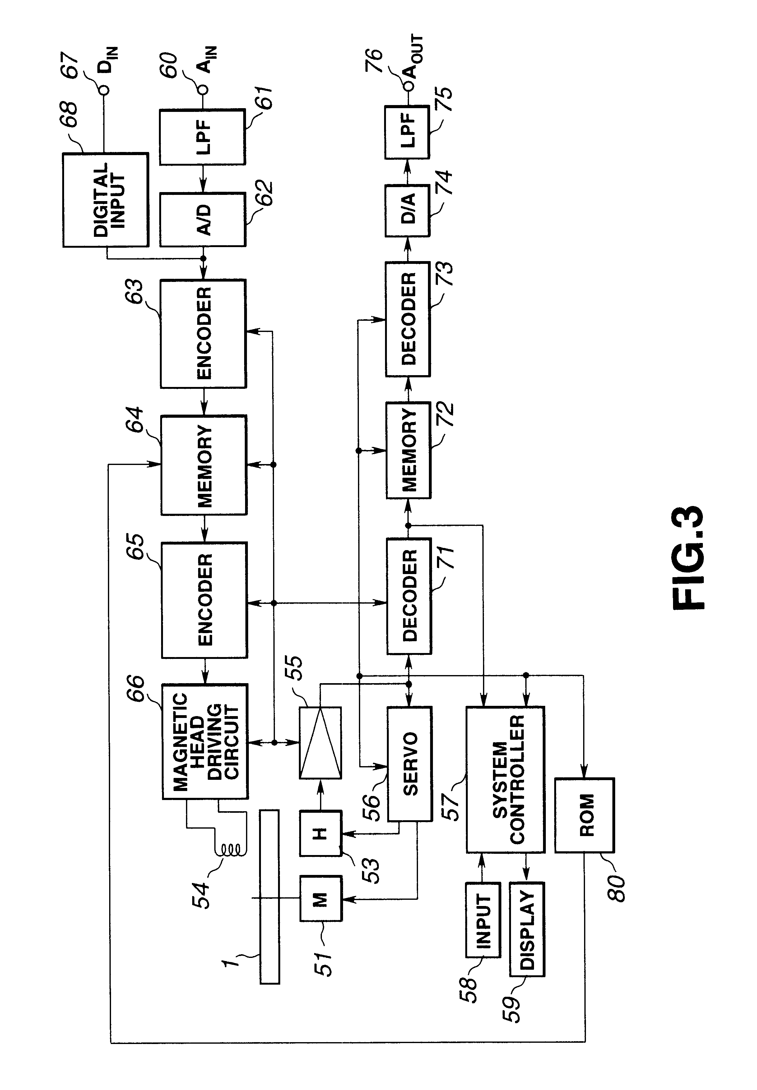
FIG. 3 shows a schematic structure of a compressed data recording and / or reproducing apparatus embodying the present invention.

In the compressed data recording and / or reproducing apparatus shown in FIG. 3, a magneto-optical disc 1, run in rotation by a spindle motor (M) 51, is used as a recording medium. For recording data on the magneto-optical disc 1, a modulated magnetic field corresponding to recording data is applied to a magnetic head 54, whilst the laser light beam is illuminated by an optical head (H) 53, by way of performing so-called magnetic field modulation recording, for recording data along the recording track of the magneto-optical disc 1. For reproduction, the recording track of the magneto-optical disc 1 is traced with the laser light beam by the optical head 53 for photomagnetic reproduction.

The optical head 53 is made up of a laser light source, such as a laser di...


PUM


Abstract

An information recording apparatus which, while enabling reproduction by an old standard accommodating reproducing device, reduces the effect of the quantization error produced on decoding at the time of encoding and decoding which realizes a multiple channel system by new standard expansion. The apparatus includes an adaptive channel conversion circuit for multiplying signals of a L or R channel with a first coefficient, multiplying signals of the other channel with a second coefficient, mixing signals of the channel multiplied with the first coefficient with signals of the channel multiplied with the second coefficient for each of the L and R channels, and for generating (L+R)/2 and (L-R)/2 from the L and R channels existing after the channel mixing. The apparatus also includes a first encoding circuit for encoding (L+R)/2 with A-codec and a second encoding circuit for encoding (L-R)/2 signal with B-codec.

Description

1. Field of the InventionThis invention relates to an encoding method and apparatus, suitable for encoding input signals by high efficiency encoding and for reproducing playback signals on transmission, recording, reproduction and decoding, and a recording medium.2. Description of the Related ArtThere has so far been proposed an information recording medium capable of recording signals such as the encoded acoustic information or the music information (referred to hereinafter as audio signals), such as a magneto-optical disc. Among methods for high-efficiency encoding of the audio signals, there are a so-called transform coding which is a blocking frequency spectrum splitting method of transforming a time-domain signal into frequency domain signals by orthogonal transform and encoding the spectral components from one frequency band to another, and a sub-band encoding (SBC) method, which is a non-blocking frequency spectrum splitting method of splitting the time-domain audio signals i...

Claims


Application Information

Patent Timeline
IPC IPC(8): H04B1/66H04S1/00
CPCH04S1/007H04B1/667G11B20/10527G11B20/00007G11B2020/10592G11B2020/00043
Inventor SHIMOYOSHI, OSAMUTSUTSUI, KYOYA
Owner SONY CORP
Why Eureka
Try Eureka