Method and apparatus for power throttling in a microprocessor using a closed loop feedback system

a microprocessor and feedback system technology, applied in the direction of instruments, heat measurement, generating/distributing signals, etc., can solve the problems of affecting the design of computer systems, and affecting the performance of microprocessors

Inactive Publication Date: 2002-07-02
INTEL CORP
View PDF35 Cites 350 Cited by
  • Summary
  • Abstract
  • Description
  • Claims
  • Application Information

AI Technical Summary

Problems solved by technology

However, as computer applications became more complex over the years to meet the demands of the computer user, the sluggish processor speeds of the past did not suffice.
Although the dramatic increase in the microprocessor's clock speed over the years has enabled the computer user to run more complex computer applications at faster speeds, it has posed problems for the computer systems designer.
Such a significant increase in clock speed causes a substantial increase in the power consumed by the microprocessor, thus requiring the need for larger and more powerful power supplies.
This "overdesign" places unnecessary guard bands in the power and thermal design of the computer, thus increasing its cost and placing various limitations on the computer user.
That is, a larger power supply adds weight and increases the size of the computer, which is particularly disadvantageous to the user of a portable computer, for example.

Method used


Image

  • Method and apparatus for power throttling in a microprocessor using a closed loop feedback system
  • Method and apparatus for power throttling in a microprocessor using a closed loop feedback system
  • Method and apparatus for power throttling in a microprocessor using a closed loop feedback system

Examples


Embodiment Construction

Illustrative embodiments of the invention are described below. In the interest of clarity, not all features of an actual implementation are described in this specification. It will of course be appreciated that in the development of any such actual embodiment, numerous implementation-specific decisions must be made to achieve the developers' specific goals, such as compliance with system-related and business-related constraints, which will vary from one implementation to another. Moreover, it will be appreciated that such a development effort might be complex and time-consuming, but would nonetheless be a routine undertaking for those of ordinary skill in the art having the benefit of this disclosure.

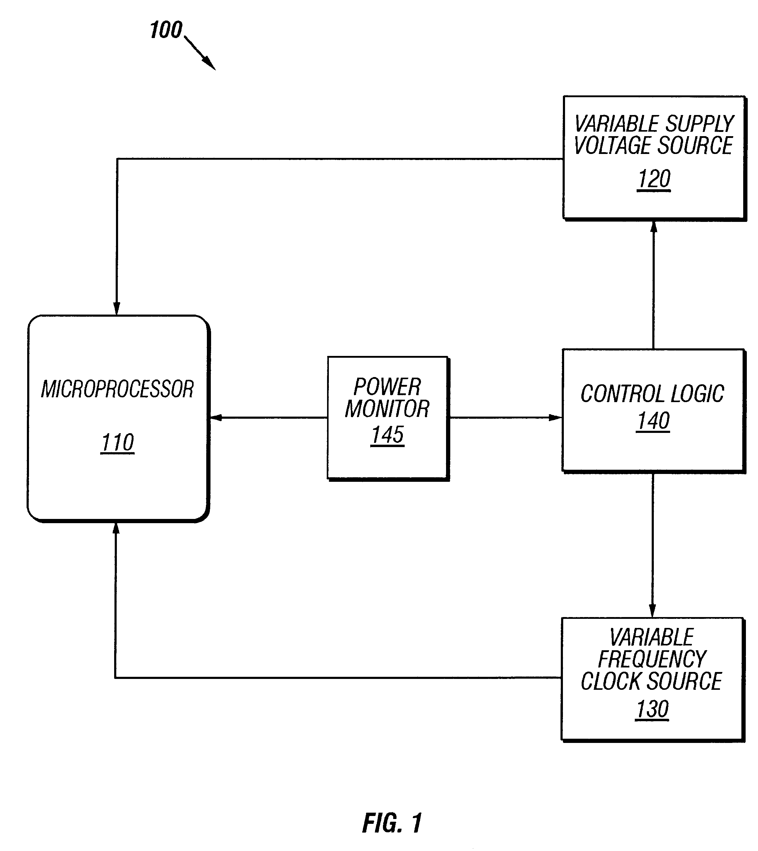
Turning now to the drawings, and specifically referring to FIG. 1, a block diagram of a power throttling closed loop feedback system 100 is shown in accordance with one embodiment of the present invention. The system 100 includes a microprocessor 110, which, in accordance with one embod...


PUM


Abstract

A method and apparatus for power throttling in a microprocessor. A voltage source supplies voltage to the microprocessor, and a clock source operates the microprocessor at a desired frequency. In one embodiment, a power monitor is configured to measure the short term power consumption of the microprocessor. In another embodiment, a temperature sensor measures the temperature of the microprocessor. Control logic is coupled to the voltage source and the clock source. The control logic receives an indication of the power consumption or temperature, as applicable, and compares it to a predetermined value. In response to the comparison, the control logic varies the supply voltage and the frequency.

Description

The present invention relates generally to computer systems architecture, and, more particularly, to a method and apparatus for power throttling in a microprocessor system using a closed loop feedback system.DESCRIPTION OF THE RELATED ARTThe clock speed of microprocessors has increased dramatically over the past several years. In the early eighties, microprocessors had clock speeds typically ranging from 5 to 16 MHz, which was sufficient to handle computer applications during that time period. However, as computer applications became more complex over the years to meet the demands of the computer user, the sluggish processor speeds of the past did not suffice. Today, microprocessors have clock speeds far exceeding those of the past, running at more than 300 MHz. And, these clock speeds show no sign of reaching a pinnacle. The microprocessors of the not-too-distant future have projected clock speeds that will significantly dwarf today's clock speed standards. With these higher clock ...

Claims


Application Information

Patent Timeline
Patent Type & Authority Patents(United States)
IPC IPC(8): G06F1/32G06F1/20G06F1/26G06F1/04
CPCG06F1/206G06F1/26G06F1/3203G06F1/3228G06F1/324G06F1/3296Y02B60/1217Y02B60/1275Y02B60/1285Y02D10/00G06F1/00
Inventor BROWNING, CHRIS S.BORKAR, SHEKHAR Y.DERMER, GREGORY E.
Owner INTEL CORP
Why Eureka
Try Eureka