Storage capacitor power supply

Inactive Publication Date: 2002-07-23
NANTONG JIANGHAI CAPACITOR CO LTD +1
View PDF16 Cites 57 Cited by
  • Summary
  • Abstract
  • Description
  • Claims
  • Application Information

AI Technical Summary

Benefits of technology

It is an object of the present invention to provide a long-lived, lightweight storage capacitor pow

Problems solved by technology

The greatest technical problem with the electric vehicle is to realize an ideal power source, i.e., a battery having a capacity comparable to an automotive engine.
However, no conventional battery can satisfy the above-described requirements.
One especially great problem is that it takes long for the prior art battery to be recharged.
In spite of this fact, the prior art battery is larger in size and heavier than the internal combustion engine.
Also, the leakage current increases.
In this way, the capacitor is adversely affected.
Another disadvantage is that the internal resistance and the maximum working volta

Method used


Image

  • Storage capacitor power supply
  • Storage capacitor power supply
  • Storage capacitor power supply

Examples


Embodiment Construction

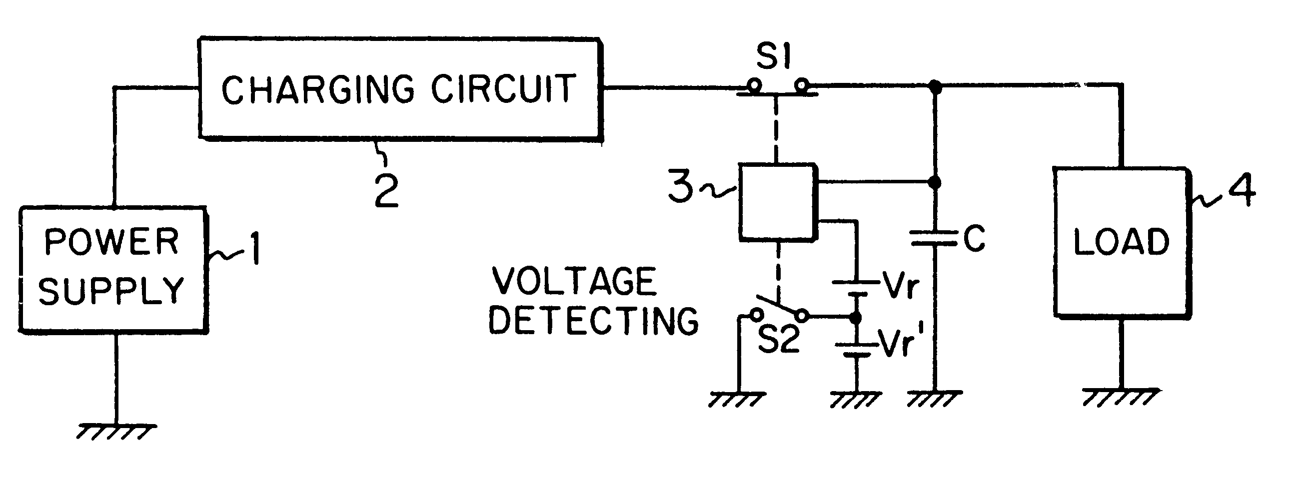
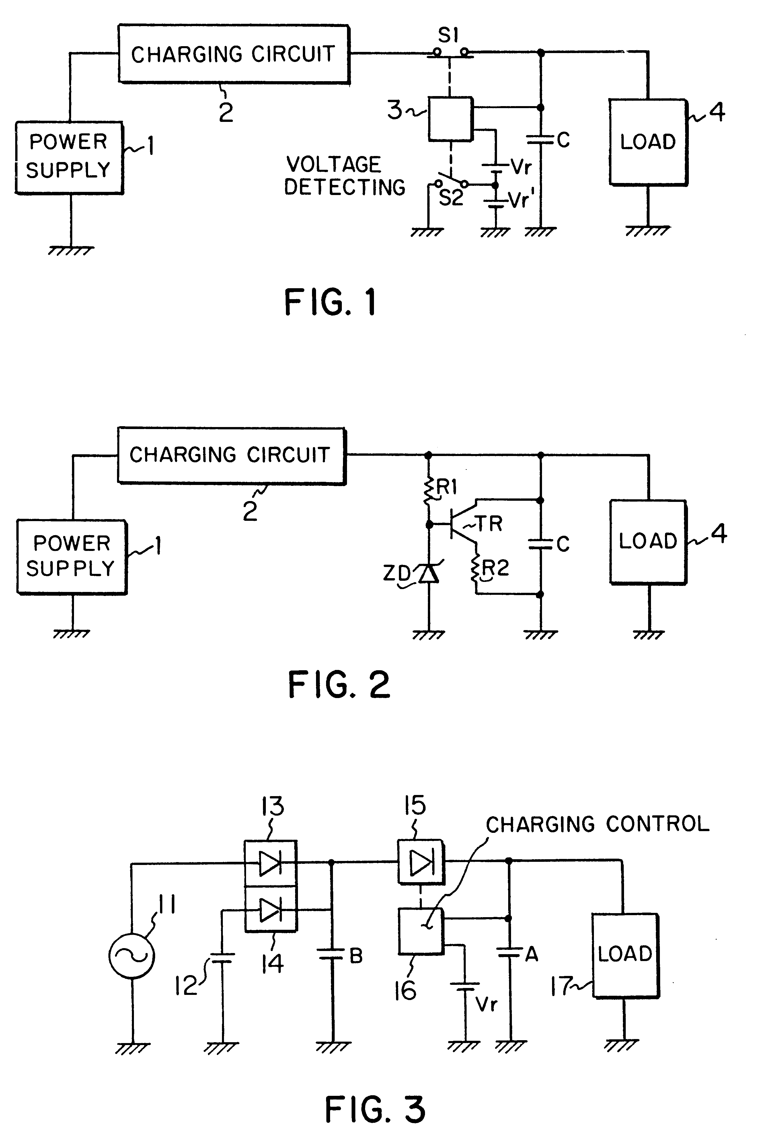
Referring to FIG. 1, there is shown a storage capacitor power supply according to the invention. This power supply comprises a charging power supply 1, a charging circuit 2, a voltage-detecting circuit 3, a capacitor C having a large capacitance, reference voltage sources producing reference voltages Vr and Vr', respectively, and switches S1 and S2. A load 4 is connected with this storage capacitor power supply.

The capacitor C having a large capacitance is connected with the charging power supply 1 via the switch S1 and via the charging circuit 2. The capacitor C is also connected with the load 4. The capacitor C supplies electric power directly to the load 4. The charging power supply 1 which acts to electrically charge the capacitor C can be the commercial power line. The charging circuit 2 has a voltage converter means such as converter. The voltage-detecting circuit 3 compares the voltage developed across the terminals of the capacitor C with the reference voltages Vr and Vr' an...


PUM


Abstract

A long-lived, lightweight, and quickly and precisely charged storage capacitor power supply capable of stably supplying electric power to a load. The power supply has a capacitor block consisting of capacitors connected in series, in parallel or in any combination of series and parallel. The power supply further includes a charging circuit for charging the block, a charging power supply connected with the block via the charging circuit, and a charge-limiting circuit. This charge-limiting circuit detects the voltage across the terminals of the block and limits charging of the block if the voltage reaches a given value. One embodiment of the invention further includes a charge-limiting circuit, a full charge-detecting circuit, and a residual electricity-detecting circuit connected in parallel with the block. The charge-limiting circuit senses that the voltage across the terminals of the block exceeds the given value and causes the charging current to bypass the block. The full charge-detecting circuit senses that the charge-limiting circuit is operated and determines that full charge is attained. The residual electricity-detecting circuit finds the residual electric power from the voltage across the terminals of the block. Another embodiment has a first and a second capacitor block. The voltage across the terminals of the first block is detected. The first block is charged from the second block until the detected voltage reaches a given voltage. The first block supplies electric power directly to the load.

Description

FIELD OF THE INVENTIONThe present invention relates to a storage capacitor power supply which stores electrical power in a capacitor block consisting of a plurality of electric double layer capacitors connected in series, in parallel or in any combination of series and parallel and supplies electrical power to a load.BACKGROUND OF THE INVENTIONDiscussions have existed for many years as to whether exhaust gas from automobiles with gasoline engines should be controlled because of problems with the global environment. In practice, the annual production of automobiles is still on the upswing but there is no prospect of reduction in automobile emissions. Under these circumstances, electric vehicles with batteries or solar cells have attracted attention as vehicles producing no exhaust gas. Therefore, there is an urgent need of early realization of practical electric vehicles.In recent years, electric vehicles have begun to be used as vehicles in business applications such as urban-delive...

Claims


Application Information

Patent Timeline
IPC IPC(8): B60L11/00B60L11/18H02J7/00H02J7/34
CPCB60L11/005B60L11/1809B60L11/1851H02J7/0016H02J7/345Y02T90/14Y02T10/7005Y02T10/7022Y02T10/705Y02T10/7055B60L50/40B60L53/00B60L53/55B60L58/10Y02T10/70Y02T10/7072Y02T90/12
Inventor OKAMURA, MICHIO
Owner NANTONG JIANGHAI CAPACITOR CO LTD
Why Eureka
Try Eureka