Flashlight mount for a firearm

a technology of flashlight and mount, which is applied in the field of flashlight mounts, can solve the problems of poor stability, difficult to comfortably grip the weapon, and suffer from the limitations of the current state of the art device, and achieve the effect of convenient and secure gripping

Inactive Publication Date: 2005-02-08
T D I ARMS SYST
View PDF17 Cites 55 Cited by
  • Summary
  • Abstract
  • Description
  • Claims
  • Application Information

AI Technical Summary

Benefits of technology

According to another embodiment, the frame includes a plurality of flattened rings around the bore, arranged for easy and secure gripping by fingers of a user.

Problems solved by technology

These prior art devices suffer from a number of disadvantages.
First, conventional flashlight mounts are substantially cylindrical in cross-section, such that their bottom surface is curved, so they provide no stability if the weapon is leaned upon a wall, for example.
However, this structure makes it difficult to comfortably grip the weapon while holding the light mount, and often places the user's hand in close proximity to the hot barrel during firing.
Thus, this location is often not optimal for users of different heights and different arm lengths.

Method used


Image

  • Flashlight mount for a firearm
  • Flashlight mount for a firearm
  • Flashlight mount for a firearm

Examples


Embodiment Construction

The present invention relates to a flashlight holder or mount for a rifle or carbine, which provides a comfortable and secure grip under the barrel, and whose location along the barrel is adjustable, relative to the stock.

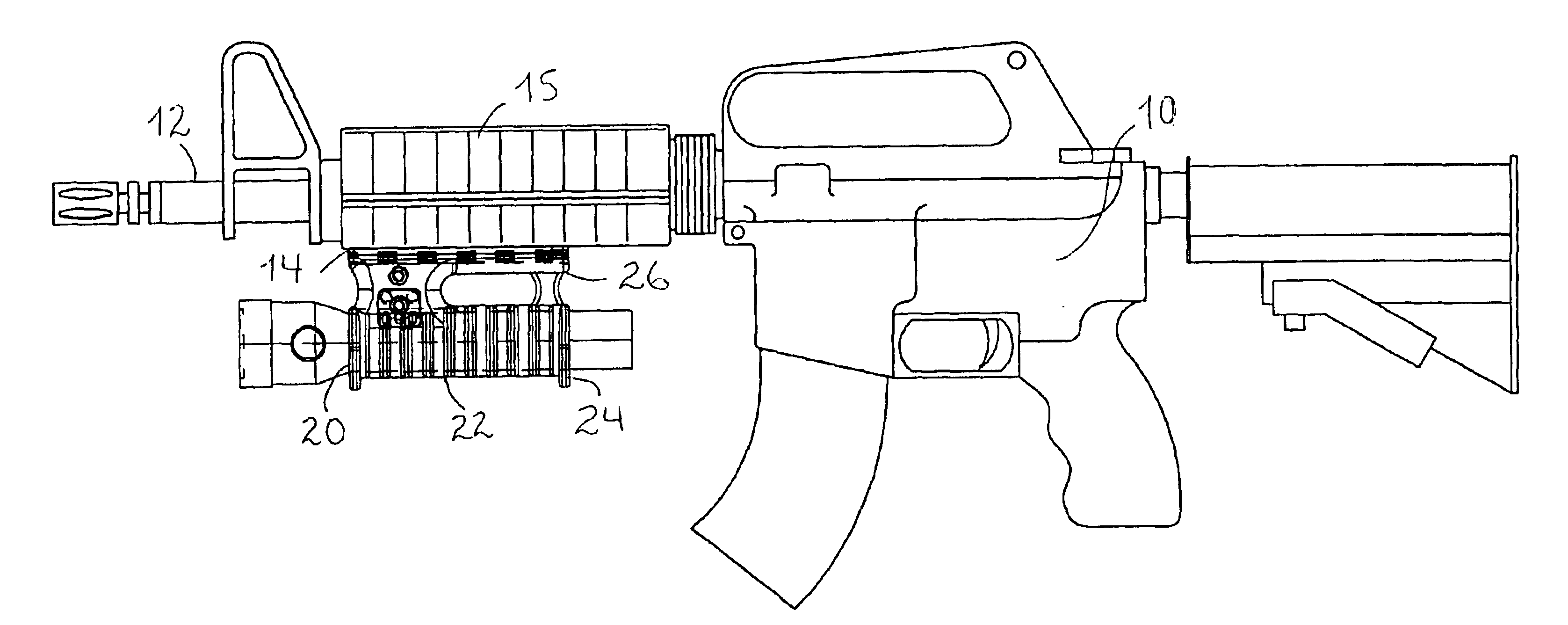
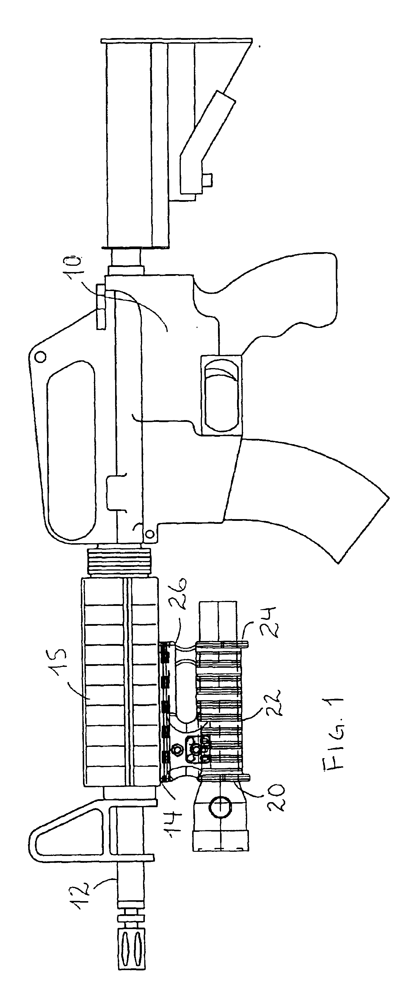
With reference to FIG. 1, there is shown a plan view of a flashlight mount 20 according to one embodiment of the invention mounted on a rifle 10 having a barrel 12 and a mounting rail 14 (which can include a rail extension) coupled to a hand guard 15 affixed around the barrel. Rifle 10 can be an M-16, or any other rifle or carbine, for which the mount of the present invention is particularly suitable. Alternatively, it will be appreciated that the mount of the present invention can be used on any hand held firearm having an elongate barrel and a mounting rail (of preferably about 10 cm or more) coupled to the barrel. Thus, for purposes of the present application, the term rifle will be used to include all these weapons.

The flashlight mount 20 includes a frame 22 ha...


PUM


Abstract

A flashlight mount, and a method for mounting a flashlight, for a rifle having a barrel and a mounting rail coupled to the barrel, the flashlight mount including a frame having a bore for receiving a flashlight, the frame defining a substantially flattened bottom surface, and a base for mounting along the mounting rail, the base being distanced from the frame, thereby creating a finger-receiving aperture therebetween.

Description

FIELD OF THE INVENTIONThe present invention relates to a light holder for mounting on a rifle, in general, and, in particular, to a flashlight mount for mounting on an existing rail structure on the weapon.BACKGROUND OF THE INVENTIONIn recent years, the increasing complexity of combat has generated a need for weapons with increased accuracy and which are capable of supporting various accessories, such as flashlights, infrared and night vision scopes, laser spotters, and so forth. Consequently, a wide variety of mounts for rifles and other hand weapons have been developed which permit the mounting of lights scopes and the like on the weapon, often along the barrel.A few examples are as follows. There is known from U.S. Pat. No. 5,590,484, to Mooney et al., a universal mount for a rifle which is formed to support a series of accessory devices simultaneously. The mount comprises an upper rail, a lower rail, a heat shield, and a retaining clip. When in place, this mount enables the rifl...

Claims


Application Information

Patent Timeline
Patent Type & Authority Patents(United States)
IPC IPC(8): F41G1/35F41G1/00
CPCF41G1/35
Inventor OZ, DAVID
Owner T D I ARMS SYST
Why Eureka
Try Eureka