Apparatus for recording signals on disk recording medium

a technology of recording medium and apparatus, applied in the field of apparatus for recording signals, can solve the problems of inability to perform recording operations of the system, inability to write toc information in the worst case, and the abrupt rise of the battery supply voltag

Inactive Publication Date: 2005-06-07
CANON KK
View PDF3 Cites 60 Cited by
  • Summary
  • Abstract
  • Description
  • Claims
  • Application Information

AI Technical Summary

Benefits of technology

[0026]It is another object of the present invention to reliably record management information such as TOC information on a recording medium without losing the management information, even when the remaining battery amount becomes insufficient during image pickup recording.

Problems solved by technology

When a series of recording operations are performed with battery driving, therefore, the battery supply voltage lowers with an abrupt rise of the consumption power upon disk access.
This sometimes makes the recording operations of the system impossible to perform.
Hence, if the battery amount remains to such an extent that a video data recording operation is marginally possible, the TOC information cannot be written in the worst case.
If the TOC information is missing, the start pointer, end pointer, attribution, and the like of recorded video data are unknown, so disk medium playback control cannot be performed.
Also, even if the reliability of the TOC data is improved as described previously, recording is sometimes abnormally terminated in the middle of a scene by, e.g., careless handling by a user, running out or abrupt discharge of a battery, a defect of a recording medium, or some external cause.
This makes playback of the scene based on the TOC impossible.

Method used


Image

  • Apparatus for recording signals on disk recording medium
  • Apparatus for recording signals on disk recording medium
  • Apparatus for recording signals on disk recording medium

Examples


first embodiment

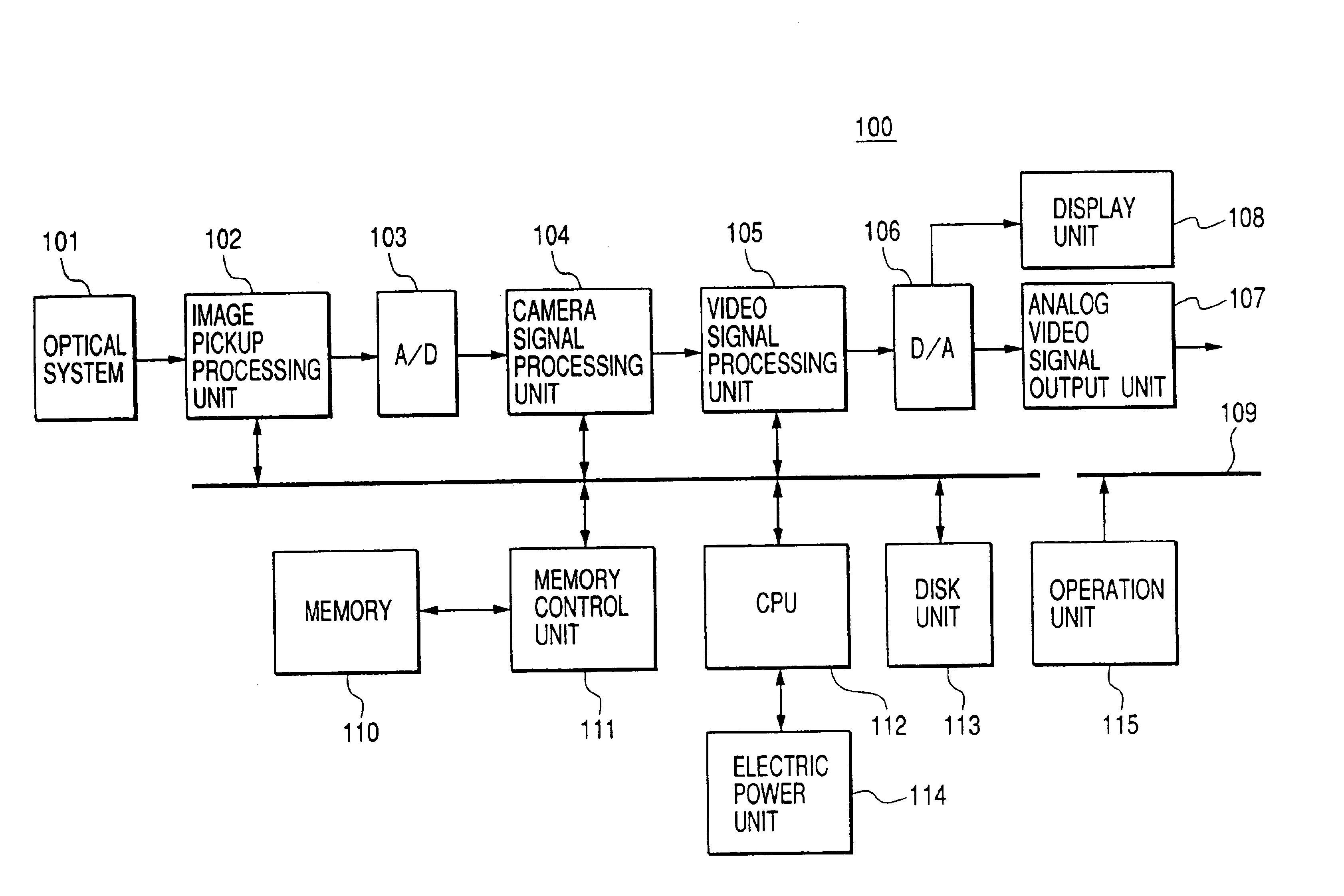
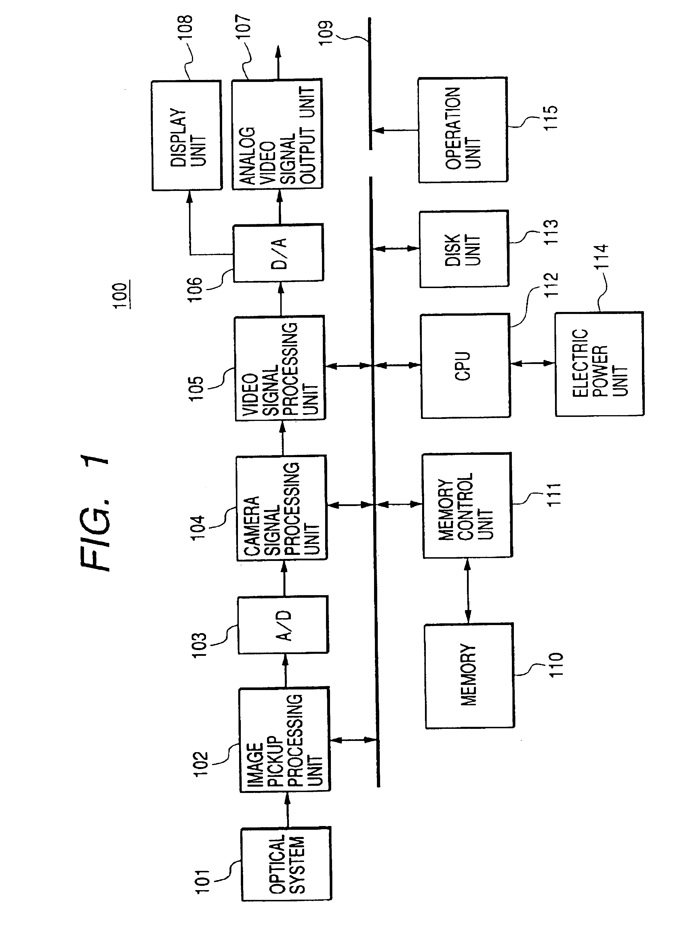
[0053]FIG. 1 is a block diagram showing the configuration of a recording / playback apparatus 100 according to the present invention. Referring to FIG. 1, this recording / playback apparatus 100 comprises an optical system 101 including, e.g., a lens and a lens controller, an image pickup processing unit 102, an A / D converter 103, a camera signal processing unit 104, a video signal processing unit 105, a D / A converter 106, an analog video signal output unit 107, a display unit 108, a data bus 109, a memory 110, a memory controller 111, a CPU 112, a disk unit 113, an electric power unit 114 such as a battery, and an operation unit 115 including, e.g., a power switch and a recording trigger switch. For the sake of simplicity, the electric power unit 114 is connected only to the CPU 112 in FIG. 1. In reality, however, electric power is supplied to all units requiring power via power lines.

[0054]In this recording / playback apparatus 100, the optical system 101 including a lens performs iris ...

second embodiment

[0092]In the second embodiment, a TOC is constructed as shown in FIG. 7. One-bit remove information indicating that this TOC information is not normally recorded and its contents do not reflect the latest recorded contents can be described in the MSBs of attribution data 402′ in a management information table portion.

[0093]Processing by a CPU 112 in this embodiment will be described below with reference to a flow chart in FIG. 8.

[0094]First, after power-on in step S801, the CPU 112 causes a disk unit 113 to read out TOC data from a system management area 901 on a disk 201 and write the TOC data in a memory 111. In step S802, the CPU 112 checks for all MSBs in the attributions 402′ of the TOC stored in the memory 111. In this embodiment, if the MSB of the attribution 402′ is “0”, this indicates that the TOC is normally recorded in the system management area 901 of the disk 201 when the last image data is recorded; if the MSB is “1”, this indicates that the TOC is not normally recorde...

third embodiment

[0105]the present invention will be described below with reference the accompanying drawings.

[0106]FIG. 10 is a block diagram showing a recording apparatus 1000 according to this embodiment of the present invention.

[0107]This recording apparatus 1000 comprises an image pickup unit 1001, a picture rearrangement circuit 1002, a switch 1003, a subtractor 1004, a DCT (Discrete Cosine Transform) circuit 1005, a quantization circuit 1006, a variable-length encoding circuit 1007, an inverse quantization circuit 1008, an IDCT (Inverse Discrete Cosine Transform) circuit 1009, an adder 1010, a motion compensation prediction circuit 1011, a switch 1012, a buffer 1013, a rate control circuit 1014, a recording processing circuit 1015, a magnetooptical disk 1016, a picture change detection circuit 1017, a TOC memory 1018 for storing TOC information, a TOC control circuit 1019, and an operation unit 1020 which includes, e.g., a power switch and a recording trigger switch.

[0108]The operation will b...


PUM

PropertyMeasurementUnit
anglesaaaaaaaaaa
areaaaaaaaaaaa
electric poweraaaaaaaaaa

Abstract

A recording apparatus of this invention detects the state of management information, which pertains to a recording address of an image signal, and which is reproduced from a disk-like recording medium having a first area for the image signal and a second area for the management information. On the basis of the detection result, management data is reproduced from the first area of the disk-like recording medium. On the basis of the management data reproduced from the first area, the management information reproduced from the second area is modified. A modify unit records the modified management information in the second area.

Description

BACKGROUND OF THE INVENTION[0001]1. Field of the Invention[0002]The present invention relates to an apparatus for recording signals such as image signals on a disk recording medium and, more particularly, to control of management information of recorded signals.[0003]2. Related Background Art[0004]Conventionally, a video tape recorder which records analog video signals on magnetic tapes is available as an image recording apparatus for recording video signals on a recording medium. However, with rapid progress of digital signal processing technologies, digital recording / playback apparatuses which record analog video signals on a recording medium by converting the signals into digital video signals are becoming popular at present.[0005]Such digital recording / playback apparatuses include a digital VTR, a digital video disk apparatus which records signals on a solid-state disk or magnetooptical disk, and a solid-state memory video apparatus which records signals in a solid-state memory ...

Claims


Application Information

Patent Timeline
Patent Type & Authority Patents(United States)
IPC IPC(8): H04N5/225H04N5/76G11B27/034G11B27/32H04N5/77H04N5/85H04N5/91H04N5/917H04N5/935H04N9/804H04N9/806H04N9/82
CPCG11B27/034G11B27/329H04N5/772H04N9/802G11B2220/2525H04N9/8042H04N9/8063H04N9/8205H04N5/85H04N5/91
Inventor SUZUKI, TOSHIHIKOHOSHI, HIDENORIENDO, HIROAKI
Owner CANON KK
Why Eureka
Try Eureka