Method for fabrication of optical element having metal ring

Inactive Publication Date: 2005-08-30
ALPS ALPINE CO LTD
View PDF2 Cites 6 Cited by
  • Summary
  • Abstract
  • Description
  • Claims
  • Application Information

AI Technical Summary

Benefits of technology

[0033]According to the present invention, when the diameter of the metal ring is expanded during molding, because the thin-wall portion is expanded when the diameter of the holding portion is expanded subsequent to the thin-wall sleeve, the diameter expansion resistance of the holding portion is mitigated so that the outside configuration of the holding portion and the portion around the holding portion are prevented from being deformed irregularly, and as the result the precision of the outside size is improved.
[0034]Furthermore, in the case of the present invention in which the holding portion having the edge potion provided with a polygonal aperture that is circumscribed to the inside periphery of the aperture is provided, because the portion between the polygonal side and the thin-wall sleeve is deformed more easily than the flange near the thin-wall portion located at the vertex of the polygon when the diameter of the holding portion is expanded, the diameter expansion resistance of the holding portion is mitigated so that the outside configuration of the holding portion and the portion around the holding portion is prevented from being deformed irregularly, and as the result the precision of the outside size is improved.
[0035]Furthermore, in the case where a softened optical material is disposed inside the metal ring and the optical surface is formed by means of press working, the metal ring disposed on the periphery is expanded outward by means of the inside pressure when the optical material disposed in the metal ring is compressed

Problems solved by technology

However, because handling of adhesive 80 is troublesome and some component evaporated from the adhesive 80 deteriorates the atmosphere around the lens when the adhesive 80 is used for fixing the lens 70, it is desired that the lens is fixed on the mounting base by means of soldering without using adhesive.
However, if the peripheral edge of a glass lens having a small diameter as described hereinabove is metalized by means of spattering technique, it is difficult to control spattering due to such a small diameter of the lens, and it is necessary to protect the optical functional surface of the lens from being metalized.
As the result, it has not been realized to manufacture the desired lens efficiently.
However, if the optical glass is heated in contact with the die material w

Method used


Image

  • Method for fabrication of optical element having metal ring
  • Method for fabrication of optical element having metal ring
  • Method for fabrication of optical element having metal ring

Examples


Example

[0045]The present invention will be described in detail hereinafter with reference to the drawings. An optical element fabricated in this example is a glass aspherical lens 1 having a metal ring as shown in FIG. 4. The glass aspherical lens 1 having a metal ring has convex surfaces 31 and 32 that are served as the optical surface, and a flange-like peripheral side surface 33 on which a metal ring 10 is attached is formed on the periphery of the optical surface.

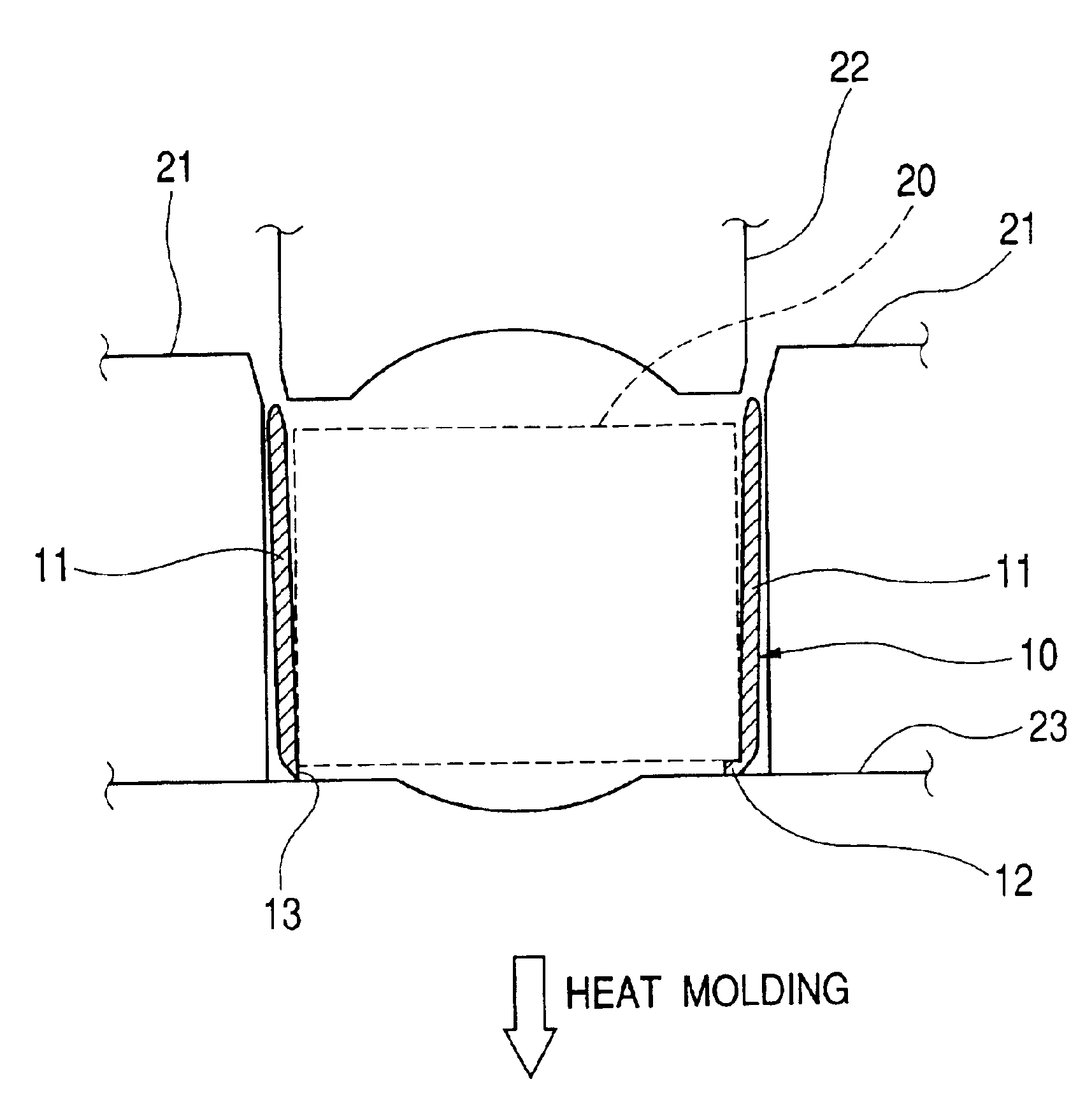
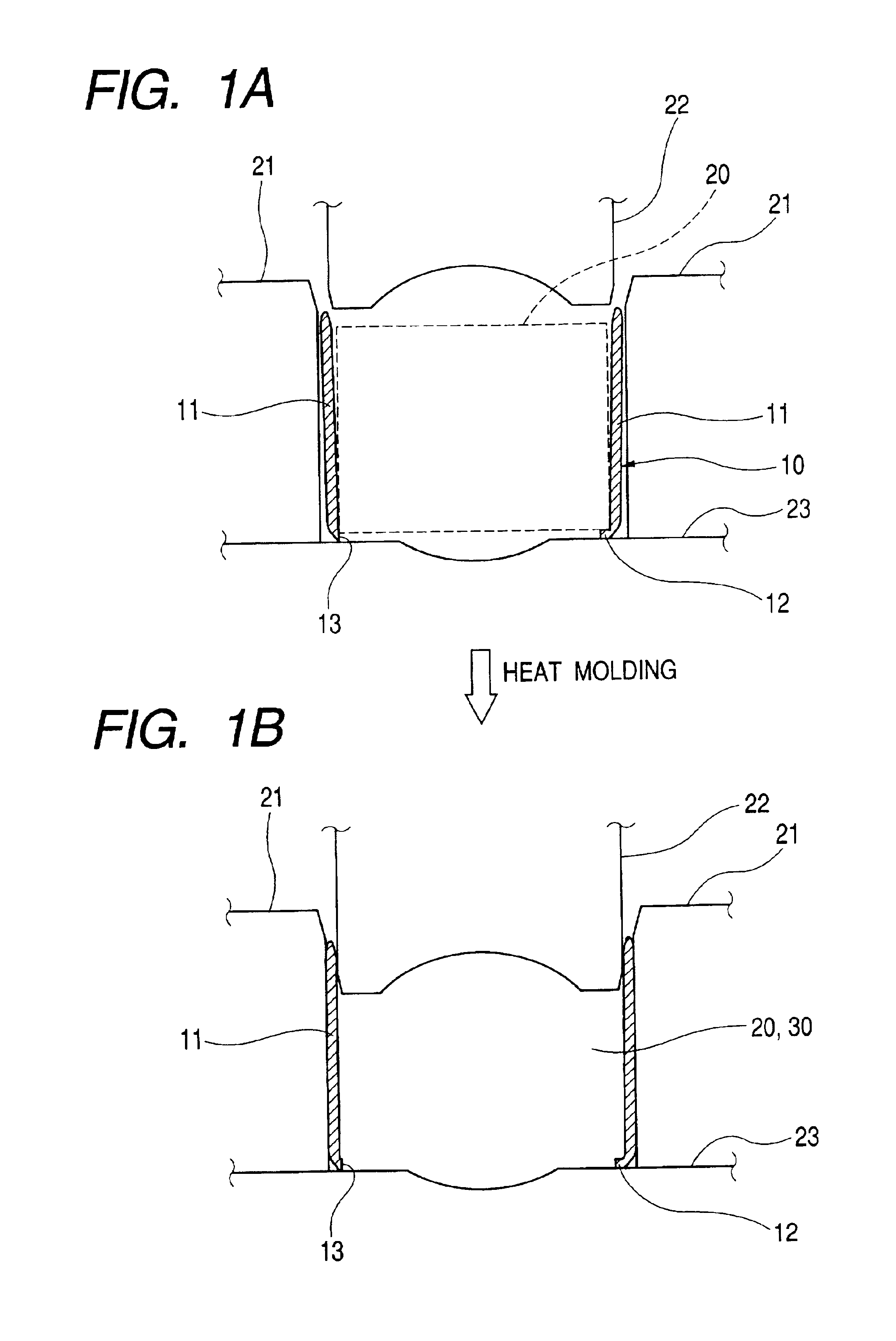
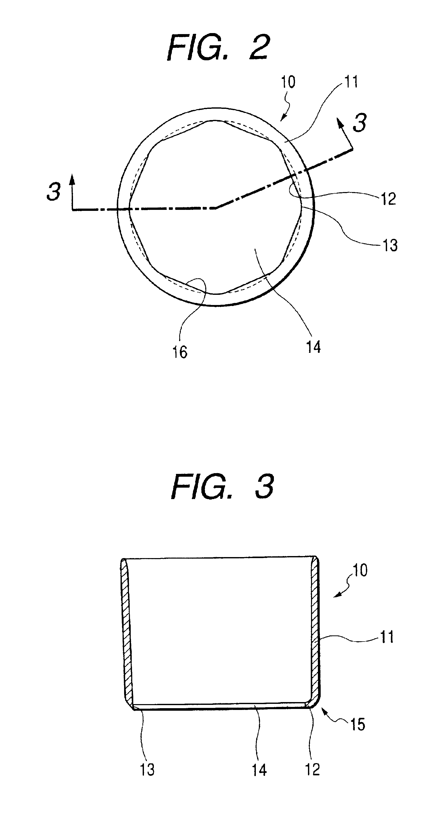
[0046]Furthermore, a thin-wall metal ring 10 consisting of, for example, metal that is easily soldered and pressed such as alloy of iron and nickel and having a desired plated layer on the surface is fitted on the peripheral side surface 33 of the glass aspherical side surface having the metal ring in accordance with the present example.

[0047]The metal ring 10 is provided with a thin-wall sleeve 11 that is to be expanded toward the peripheral direction by means of pressure exerted from the inside so that the final peripheral s...


PUM


Abstract

A metal ring for an optical element that is served to cover a peripheral side surface of a lens and served to fix the lens to a mounting member by means of soldering is provided with a thin-wall sleeve a diameter of which is expanded toward a peripheral direction by means of pressure received from an optical material disposed inside the metal ring to thereby obtain a final peripheral side surface size, a thin-wall portion having an inside periphery near an extension of an inside peripheral surface of the thin-wall sleeve on one of apertures of the thin-wall sleeve, and a holding portion comprising a flange that projects from an edge of the aperture toward the aperture. A metal ring for an optical element, a method for fabrication of the optical element having the metal ring, and an optical element having a metal ring of the invention employ the abovementioned metal ring.

Description

BACKGROUND OF THE INVENTION[0001]1. Field of the Invention[0002]This invention relates to a metal ring for an optical element, a method for fabrication of an optical element having a metal ring, and an optical element having a metal ring, and more particularly relates to a metal ring for an optical element, a method for fabrication of an optical element having a metal ring, and an optical element having a meal ring that are applied to an optical element having optical surfaces on both sides and provided with a peripheral side surface formed as the circumference of the optical element which is to be positioned on a mounting member.[0003]2. Description of the Related Art[0004]It has been proposed to use a V-groove 60 in which an aspherical lets 70 formed of optical glass having a small diameter of, for example, 1 mm as the conventional optical element as shown in FIG. 6, FIG. 7, and FIG. 8. The lens 70 is disposed in the V-groove 64 of a mounting base 62 disposed on a pedestal 61 so a...

Claims


Application Information

Patent Timeline
IPC IPC(8): C03B11/14C03C27/02C03C27/00G02B7/02C03B11/00C03B11/06
CPCC03B11/14C03C27/02G02B7/026
Inventor OTSUKI, MOTOHIKOKIKUCHI, KIMIHIRO
Owner ALPS ALPINE CO LTD
Why Eureka
Try Eureka