Motorcycle lift

a technology for motorcycles and lifts, applied in the direction of loading/unloading vehicles, transportation items, lock applications, etc., can solve the problems of not being able to fully upright the motorcycle, not providing sufficient stability for carrying out the required maintenance, etc., and achieve the effect of being ready for storage and/or transportation

Inactive Publication Date: 2005-08-30
TC DEVMENT & DESIGN
View PDF22 Cites 25 Cited by
  • Summary
  • Abstract
  • Description
  • Claims
  • Application Information

AI Technical Summary

Benefits of technology

[0023]In a preferred lift, the front and rear end lift assemblies are pivotally connected to the frame and are pivotal downwardly onto the frame to fold flat. In this manner, the lift is readily prepared for storage and / or transport. The lift can be mounted to a scissor lift to raise the entirety of the lift upward from the ground. For local transport, casters can be mounted to the frame.

Problems solved by technology

This may not be desirable in that maintenance may be required to the stand, or the stand may not provide sufficient stability for carrying out the required maintenance.
Additionally, these lifts do not permit positioning the motorcycle fully upright to, for example, drain all of the motor oil from the engine.
While this may provide the desired elevation of the motorcycle, it may not provide the necessary stability vis-à-vis preventing the motorcycle from rolling.
As such, these lifts can provide a hazard in that the elevated motorcycle can roll from the lift.
In addition, such lifts do not provide the required access to the wheels to, for example, remove a wheel.
Again, these lifts suffer from the same stability drawbacks as those that utilize the motorcycle stands.
Still other lifts are known that provide the ability to lift either the front wheel or the rear wheel of the motorcycle; however, these lifts do not provide the ability to lift either or both the front and rear wheels, independently of one another, while the other wheel is either on the lift surface, or elevated from the surface.

Method used


Image

  • Motorcycle lift
  • Motorcycle lift
  • Motorcycle lift

Examples


Embodiment Construction

[0034]While the present invention is susceptible of embodiment in various forms, there is shown in the drawings and will hereinafter be described a presently preferred embodiment with the understanding that the present disclosure is to be considered an exemplification of the invention and is not intended to limit the invention to the specific embodiment illustrated. It should be further understood that the title of this section of this specification, namely, “Detailed Description Of The Invention”, relates to a requirement of the United States Patent Office, and does not imply, nor should be inferred to limit the subject matter disclosed herein.

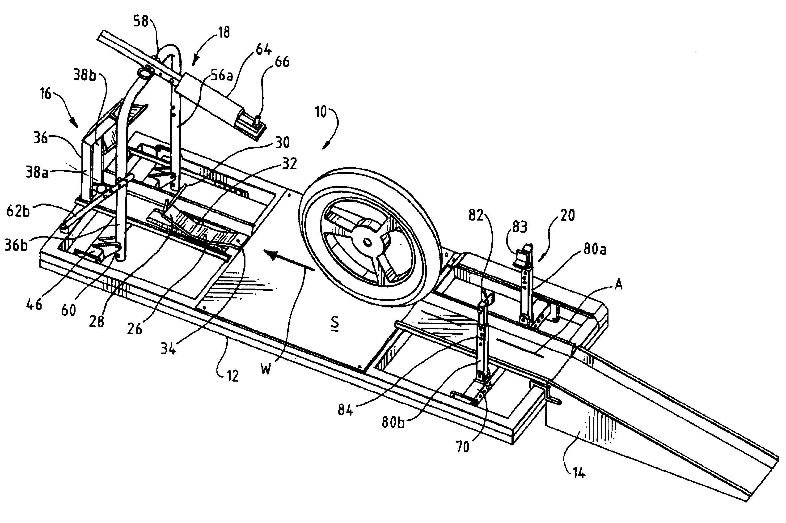
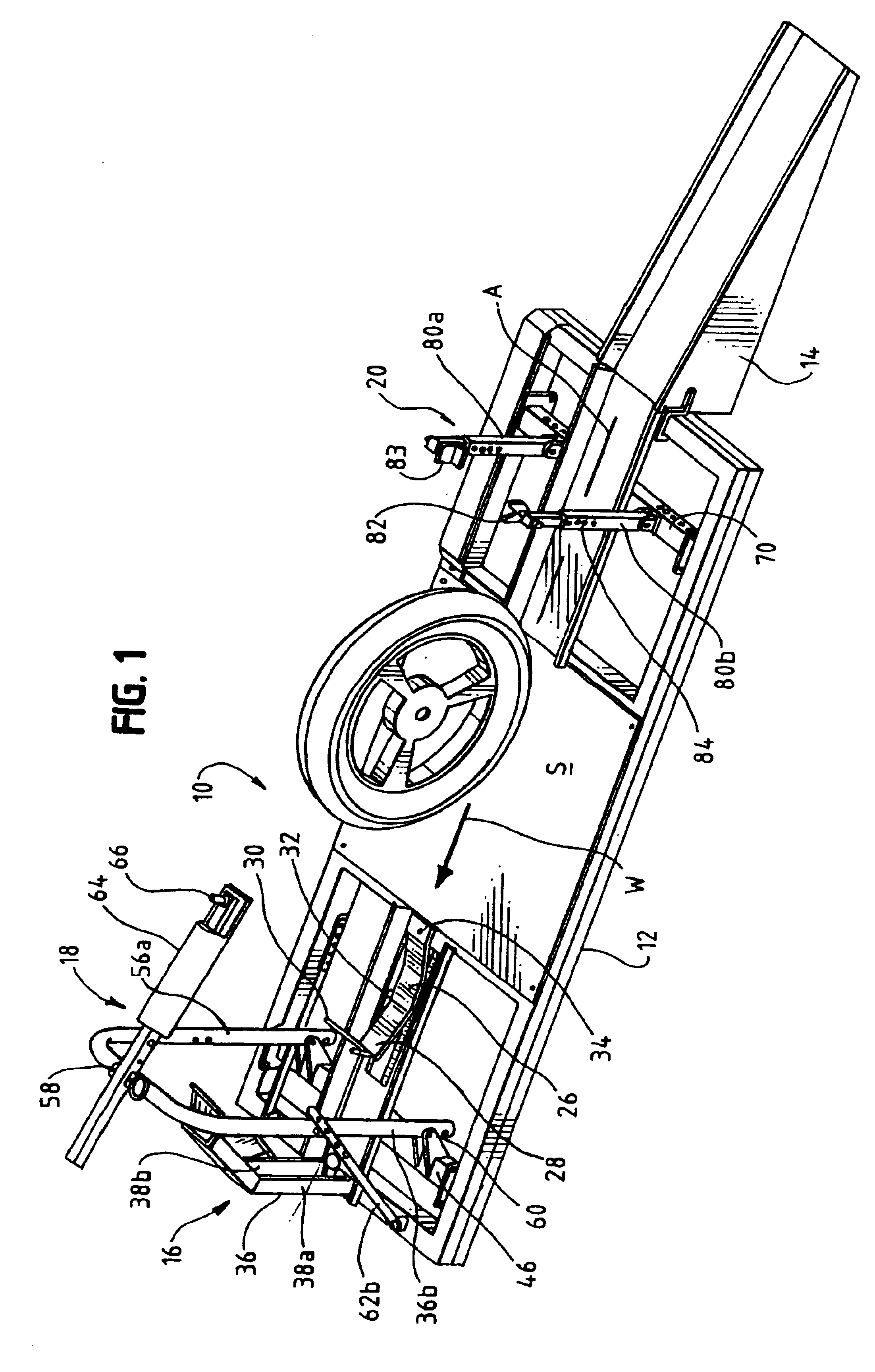
[0035]Referring now to the figures and in particular to FIG. 1 there is shown generally a motorcycle lift 10 embodying the principles of the present invention. The motorcycle lift 10 includes, generally, a frame 12 and an entrance ramp 14. Mounted to the frame 12, the lift 10 includes a front wheel locking assembly 16, a front end lift assemb...


PUM


Abstract

A lift for raising a motorcycle positioned on a surface of the lift includes a frame defining a wheel-way and a surface along a longitudinal path on the lift. A front end lift assembly includes a drive and is mounted to the frame for living the front portion of the motorcycle from the surface. A rear end lift assembly is mounted to the frame and includes a drive, independent of the front end drive, for lifting the rear portion of the motorcycle from the surface. The front and rear end lift assemblies are operable independently of one another so that the front portion of the motorcycle can be raised from the surface while the rear portion is on the surface, the rear portion of the motorcycle can be raised from the surface while the front portion is on the surface, and either the front or rear portion can be raised from the surface, independently of the other, and when the other portion of the motorcycle is raised from the surface.

Description

CROSS REFERENCE TO RELATED APPLICATIONS[0001]This application is a continuation of U.S. patent application Ser. No. 10 / 337,165, filed Jan. 6, 2003, now U.S Pat. No. 6,648,300 which is a divisional application of U.S. patent application Ser. No. 09 / 780,553, filed Feb. 9, 2001, now U.S. Pat. No. 6,575,310.BACKGROUND OF THE INVENTION[0002]The present invention pertains to a portable motorcycle lift. More particularly, the present invention pertains to a portable motorcycle lift that permits securely lifting the front and rear ends of the motorcycle independently of one another, and further permits stabilized securing of the of the motorcycle in an upright position.[0003]Motorcycle jacks or lifts are known in the art. These devices are used to elevate a motorcycle in order to, for example, perform maintenance on the motorcycle, such as, engine repair, tire changing and the like.[0004]Typically, it is desired to lift the motorcycle to an elevation at which it is comfortable for an indivi...

Claims


Application Information

Patent Timeline
Patent Type & Authority Patents(United States)
IPC IPC(8): B66F3/08B66F3/00
CPCB66F3/08Y10S224/924B66F7/243
Inventor CHAMOUN, TEFFY R.
Owner TC DEVMENT & DESIGN
Why Eureka
Try Eureka