Electric power steering apparatus

a technology of electric power steering and electric motor, which is applied in the direction of electrical steering, vehicle components, gearing, etc., can solve the problems of belt vibration and noise, and achieve the effect of reducing vibration and nois

Inactive Publication Date: 2005-09-06
KOYO SEIKO CO LTD +1
View PDF20 Cites 30 Cited by
  • Summary
  • Abstract
  • Description
  • Claims
  • Application Information

AI Technical Summary

Benefits of technology

[0008]An object of the present invention is to provide an electric power steering apparatus capable of reducing vibration and noise.
[0010]According to the present invention, the tension of the belt is properly adjusted, thereby making it possible to prevent inferior operation and noise generation caused by too much slack in the belt.

Problems solved by technology

However, vibration may be generated in the belt due to fluctuations in the tension of the belt, and transmitted to a housing to propagate into a vehicle chamber, to be noise.

Method used


Image

  • Electric power steering apparatus
  • Electric power steering apparatus
  • Electric power steering apparatus

Examples


first embodiment

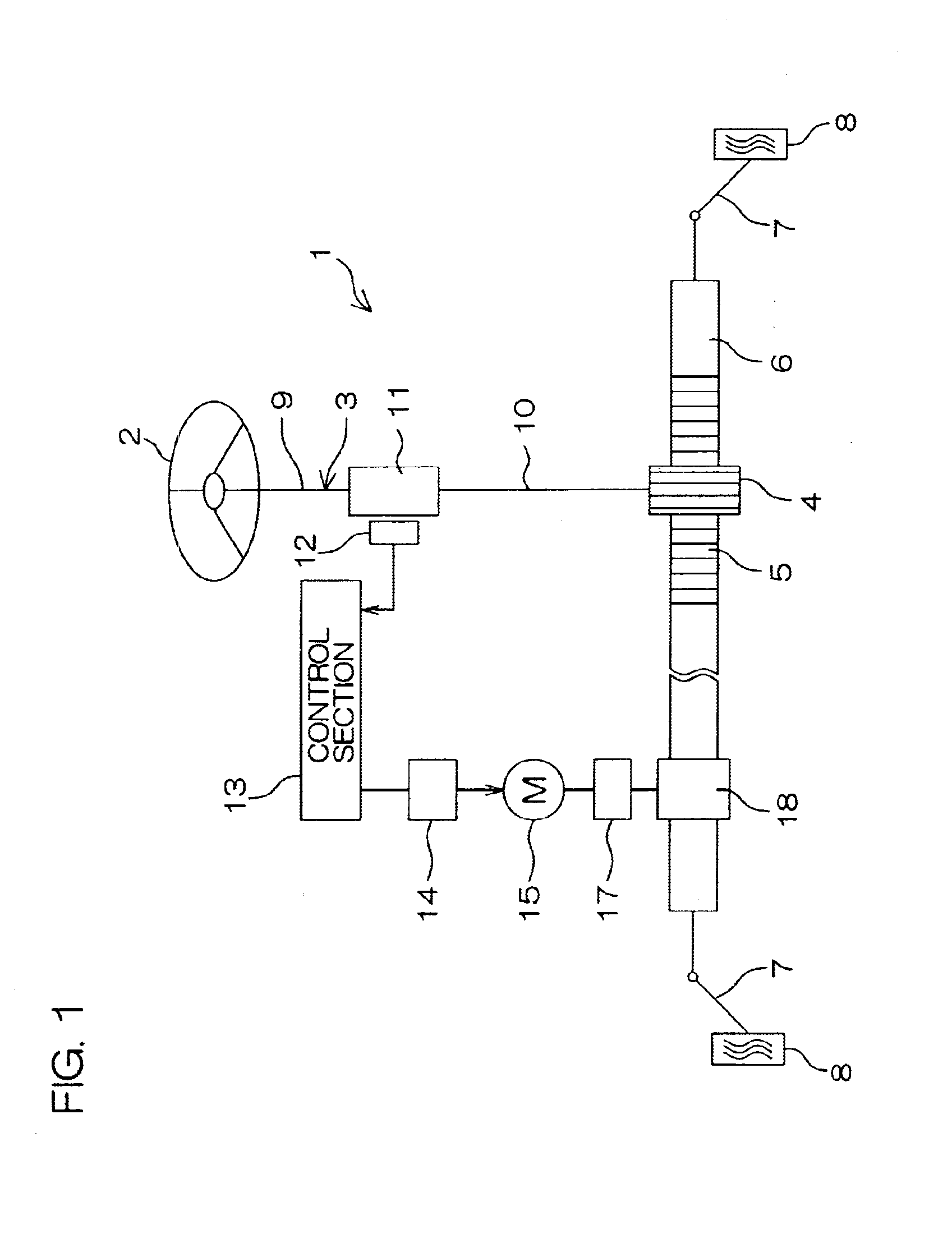
[0033]FIG. 1 is a schematic view showing the schematic configuration of an electric power steering apparatus according to a first embodiment of the present invention. Referring to FIG. 1, an electric power steering apparatus (EPS) 1 comprises a steering shaft 3 connected to a steering wheel 2 serving as a steering member, and a rack shaft 6 serving as a steering shaft having a pinion gear 4 provided at a front end of the steering shaft 3 and a rack gear 5 engaging with the pinion gear 4 and extending toward the right and left sides of a vehicle.

[0034]Tie rods 7 are respectively coupled to both ends of the rack shaft 6. Each of the tie rods 7 is connected to a corresponding wheel 8 through a corresponding knuckle arm (not shown). When the steering wheel 2 is operated so that the steering shaft 3 is rotated, the rotation is converted into the linear motion of the rack shaft 6 along the right and left sides of the vehicle by the pinion gear 4 and the rack gear 5. Consequently, the roll...

second embodiment

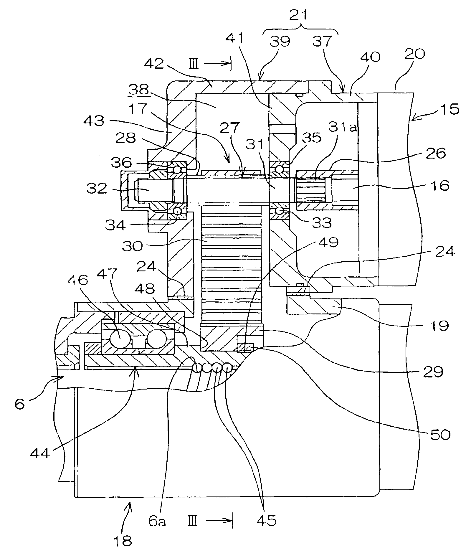
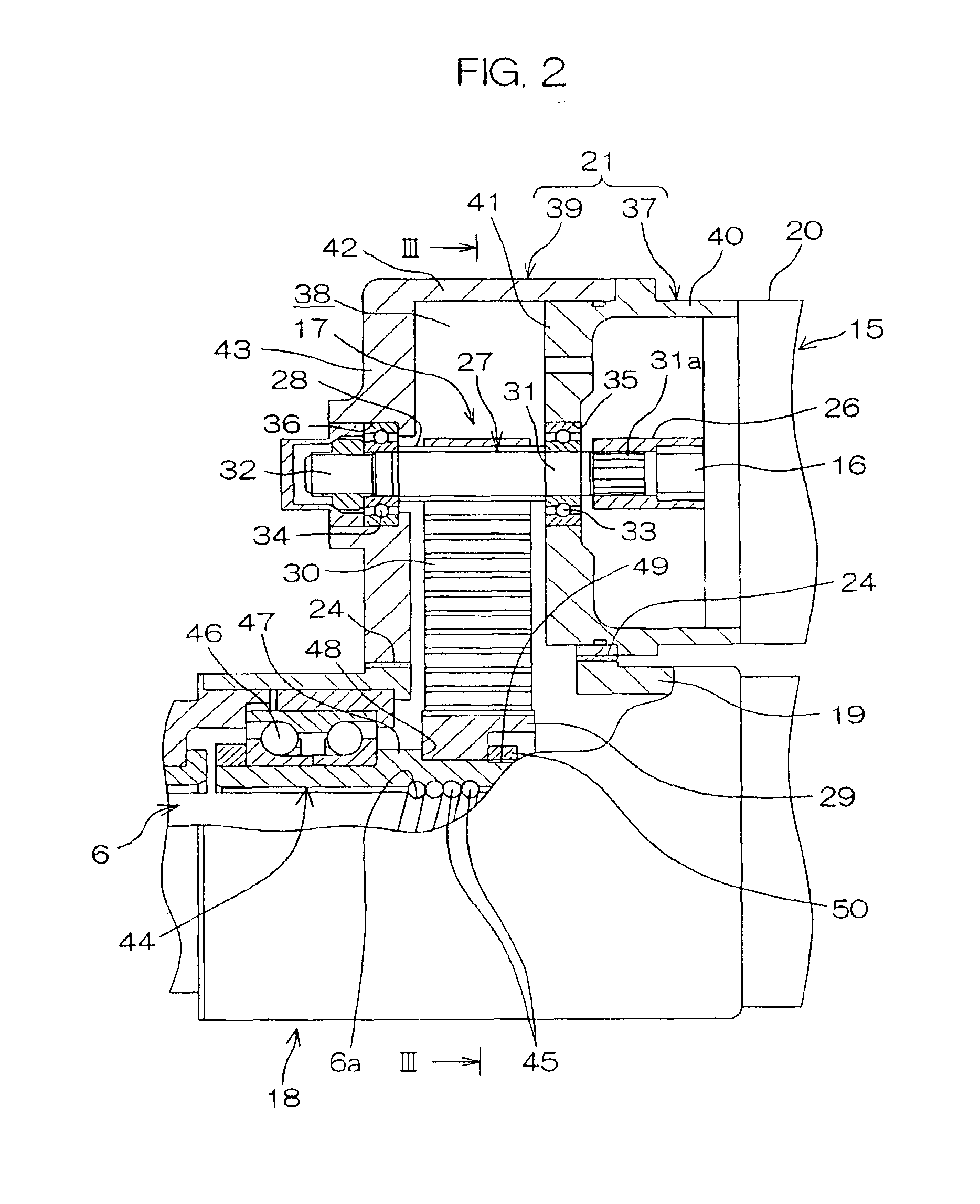
[0050]Then, FIG. 4 illustrates a second embodiment of the present invention. Referring to FIG. 4, the present embodiment differs from the first embodiment shown in FIG. 3 in that the spacer 24 is abandoned, and a first housing 21 for holding an input pulley 28 and a rack housing 19 serving as a second housing for holding an output pulley 29 through a bearing 46 and a rack shaft 6 are relatively slid in a lateral direction X along their mounting flanges 22 and 23 to adjust a center-to-center distance D between respective center axes 28a and 29a of the input and output pulleys 28a and 29a. The lateral direction X is a direction approximately perpendicular to a plane P including the center axes 28a and 29a.

[0051]In order to allow the foregoing, a screw insertion hole 22b of the mounting flange 22 is formed into a slot along the lateral direction X, to guide the relative slide between both the housings 19 and 21 in the lateral direction X through the screw insertion hole 22b composed o...

third embodiment

[0053]Then, FIG. 5 illustrates a third embodiment of the present invention. Referring to FIG. 5, the third embodiment differs from the second embodiment shown in FIG. 4 in that both the housings 21 and 19 are relatively slid along a lateral direction X in the second embodiment shown in FIG. 4, while a rack housing 19 and a connection housing 37A are relatively slid along a longitudinal direction Y to adjust a center-to-center distance D, and there is provided a single drive screw 51 for relatively sliding the rack housing 19 and the connection housing 37A along the longitudinal direction Y in the present embodiment. The longitudinal direction Y is a direction approximately perpendicular to both a center axis 28a and a center axis 29a.

[0054]Specifically, there is provided a guided section 52 composed of an outward annular flange in a peripheral wall 40 of the connection housing 37A, and there is provided an extended section 53 extending parallel to an input shaft 27 from an end wall...


PUM


Abstract

An electric power steering apparatus includes a speed reducing mechanism for decelerating the rotation of a rotatable shaft in an electric motor and a converting mechanism for converting the output rotation of the speed reducing mechanism into the axial movement of a steering shaft extending toward the right and left sides of a vehicle. The speed reducing mechanism includes an input pulley driven by the electric motor, an output pulley arranged with the steering shaft enclosed thereby, a belt for connecting the input pulley and the output pulley to each other, and a belt tension adjuster.

Description

CROSS REFERENCE TO RELATED APPLICATIONS[0001]The present invention corresponds to and claims benefit of applications No. 2002-020347 and No. 2002-020346 filed with the Japan Patent Office on Jan. 29, 2002, an application No. 2002-040327 filed with the Japan Patent Office on Feb. 18, 2002, and an application No. 2002-044911 filed with the Japan Patent Office on Feb. 21, 2002, all the disclosures of which are hereby incorporated by reference.BACKGROUND OF THE INVENTION[0002]1. Field of the Invention[0003]The present invention relates to an electronic power steering apparatus that generates a steering assist force by an electric motor.[0004]2. Description of Related Arts[0005]In a rack assist type electronic power steering apparatus, the rotation of an electric motor is decelerated through a pulley / belt mechanism, and is then converted into the axial movement of a rack shaft through a screw ball mechanism enclosing a rack shaft (see JP-B-4-28583, for example).[0006]In this case, a belt...

Claims


Application Information

Patent Timeline
Patent Type & Authority Patents(United States)
IPC IPC(8): B62D5/04F16H7/10F16H7/14F16H7/08F16H7/12
CPCB62D5/0424B62D5/0448F16H7/14F16H7/1281F16H2007/0806F16H2007/088F16H2025/2096B62D5/04
Inventor SASAKI, HIROTOSARUWATARI, TAKEHIRONAKAMURA, KENSAKUMIYATA, ATSUYANAGAMATSU, KAZUAKIOKA, KUNIHIROMURATAKA, HIROSHIHIRONAKA, AKIHIRO
Owner KOYO SEIKO CO LTD
Why Eureka
Try Eureka