Endoscopic device for locomotion through the gastro-intestinal tract

a tubular body cavity and endoscopic technology, applied in the field of endoscopic devices for locomotion through the tubular body cavity, can solve the problems of insufficient anchorage to the cavity wall, severe pain for the patient, and inability to produce sufficient traction forces

Inactive Publication Date: 2005-09-06
ERA ENDOSCOPY
View PDF8 Cites 50 Cited by
  • Summary
  • Abstract
  • Description
  • Claims
  • Application Information

AI Technical Summary

Benefits of technology

[0008]Another object of the present invention is to provide an endoscopic device of the above mentioned type for achieving a suitable anchorage to the cavity wall by means of structurally simple solutions allowing the size of the device to be kept small.
[0011]The main advantage of the endoscopic device of the invention consists in that it can migrate through a tubular body cavity in every condition whatever the available friction forces and the compliance of the body cavity are

Problems solved by technology

When the endoscopic device of the type described in the above cited patents is destined to the locomotion through the gastro-intestinal tract, its anchorage to the cavity walls is not satisfactory, because this type of cavity is soft, slippery and often wet.
Using balloon-type endoscopic devices such that according to U.S. Pat. No. 5,298,670, even if the intestinal wall is overextended, it is impossible to produce sufficient traction forces due to extremely low friction coefficient of the gastrointestinal tract.
Furtheremore, excessive overextension of the balloon will result in causing severe pain for the patient.
A similar result is obtained by increasing the suction in the case of the endoscopic device of U.S. Pat. No. 5,906,591, with the drawback that, when the degree of vacuum is increased over a certain extent, undesirable lesions may appear.
In order to improve the anchorage of the endoscopic devices of the above mentioned type it has proposed to equip them with auxiliary anchoring means of various shapes, which, however, increase the structural complexity and the length of the device and increase the patient discomfort and the risk of damage of the involved tissues.

Method used


Image

  • Endoscopic device for locomotion through the gastro-intestinal tract
  • Endoscopic device for locomotion through the gastro-intestinal tract
  • Endoscopic device for locomotion through the gastro-intestinal tract

Examples


Embodiment Construction

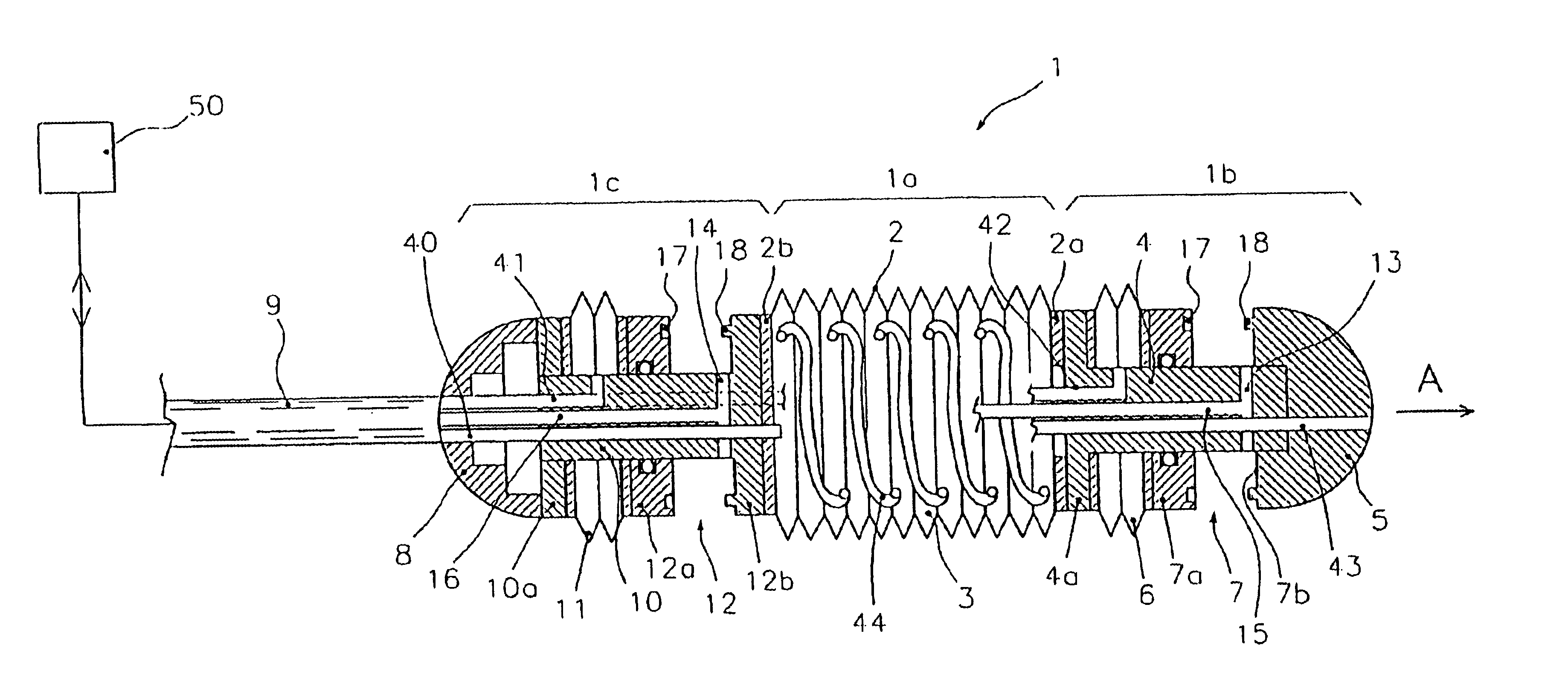
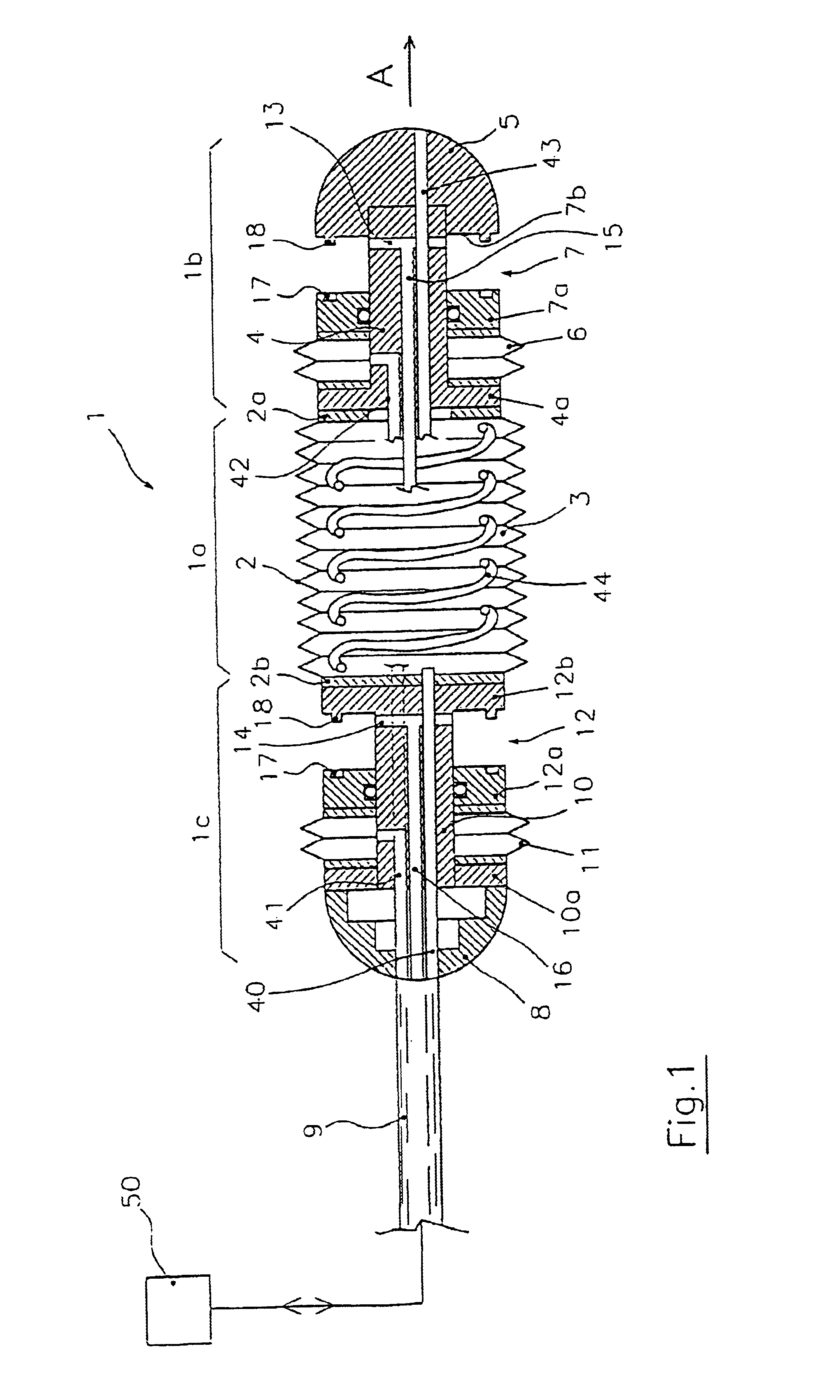
[0021]With reference to FIG. 1, it has been generally indicated at 1 an endoscopic device according to the present invention. It comprises an intermediate section 1a of a tubular shape, extending between two end sections called front end section 1b and rear end section 1c, the terms “front” and “rear” being referred to a reference direction indicated at A. Clearly, the endoscopic device will be able to move in the body cavity in a forward and a backward direction. The tubular intermediate section 1a is formed by a wall 2 made of elastic and flexible material shaped like a bellows and delimiting a cavity 3 for containing a fluid, for example air. The intermediate section ends with a front flange 2a and a rear flange 2b through which it is connected to front end section 1b and rear end section 1c respectively.

[0022]Front end section 1b of the device is formed by a stem 4 fixed to front flange 2a at a flanged end 4a thereof and to a front head 5 of the device at the other end. Fixed to...


PUM


Abstract

An endoscopic device for locomotion in a body cavity according to a prefixed advancing direction (A) comprising at least a variable length intermediate section (1a, 21a) extending between a front end section (1b, 21b) and a rear end section (1c, 21c). First and second clamping means (7, 12, 27, 32) are integral to the front and rear section, for alternately grasping respective surrounding portions of wall (P) of the body cavity. Sucking means (13, 14, 37, 38) are associated to the first and second clamping means for creating a depression sufficient to cause the body cavity wall portions to collapse within the first and second clamping means while they are in an open condition. Means for actuating alternate extensions and retractions of the intermediate section and actuating means (6, 11, 26, 31) of the first and second clamping means are further provides for synchronous operation to generate a forward motion of the rear end section due to a retraction of the intermediate section, the wall portion (P) surrounding the first clamping means being firmly held therebetween, and to generate a forward motion of the front end section due to an extension of the intermediate section, the wall portion (P) surrounding the second clamping means being firmly held therebetween.

Description

FIELD OF THE INVENTION[0001]The present invention relates to an endoscopic device for locomotion through a tubular body cavity, in particular, but not exclusively, through the gastrointestinal tract, able to migrate in a prefixed direction with so-called inchworm motion.BACKGROUND OF THE INVENTION[0002]Endoscopic devices for surgical or diagnostic procedure are already known. These devices are operated by the surgeon who directly imparts to the device the forward motion through the patient's body. Surgical and / or diagnostic instruments which are necessary to carry out each specific procedure, such as microarms, microcameras, and / or laser emitters are generally associated to these devices.[0003]In order to make easier the surgeon's task there have been proposed endoscopic devices of the above mentioned type capable of a semi-autonomous movement within the body cavity of a patient, adapting their shape, as far as possible, to the shape of the surrounding cavity. In this case, the wall...

Claims


Application Information

Patent Timeline
Patent Type & Authority Patents(United States)
IPC IPC(8): A61B1/00A61M25/01A61M25/08
CPCA61M25/0116A61B1/00151A61B1/015
Inventor PHEE SOO JAY, LOUISARENA, ALBERTOMENCIASSI, ARIANNADARIO, PAOLO
Owner ERA ENDOSCOPY
Why Eureka
Try Eureka