Decorative capped wheel nut and method of assembly

Inactive Publication Date: 2005-10-25
INDAL & AUTOMOTIVE FASTENERS L L C
View PDF33 Cites 28 Cited by
  • Summary
  • Abstract
  • Description
  • Claims
  • Application Information

AI Technical Summary

Benefits of technology

[0009]The improved method of retaining a cap on the insert body requires only two components, the cap and the insert, thus reducing the extra expense of an additional component and the complexities of introducing this extra component into the assembly process. It also allows

Problems solved by technology

All methods described in the prior art require relatively complex structures, assembly procedures and/or additional components.
Assemblies produced by welding require expensive and sophisticated equipment for practical implementation of production.
Practical options for plating the inserts are limited where welding is employed, placing welded designs at a

Method used


Image

  • Decorative capped wheel nut and method of assembly
  • Decorative capped wheel nut and method of assembly
  • Decorative capped wheel nut and method of assembly

Examples


first embodiment

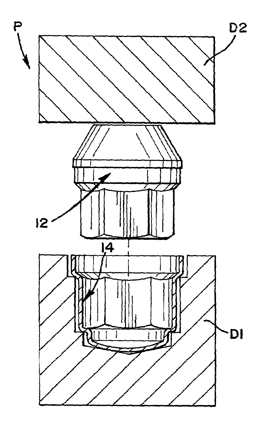
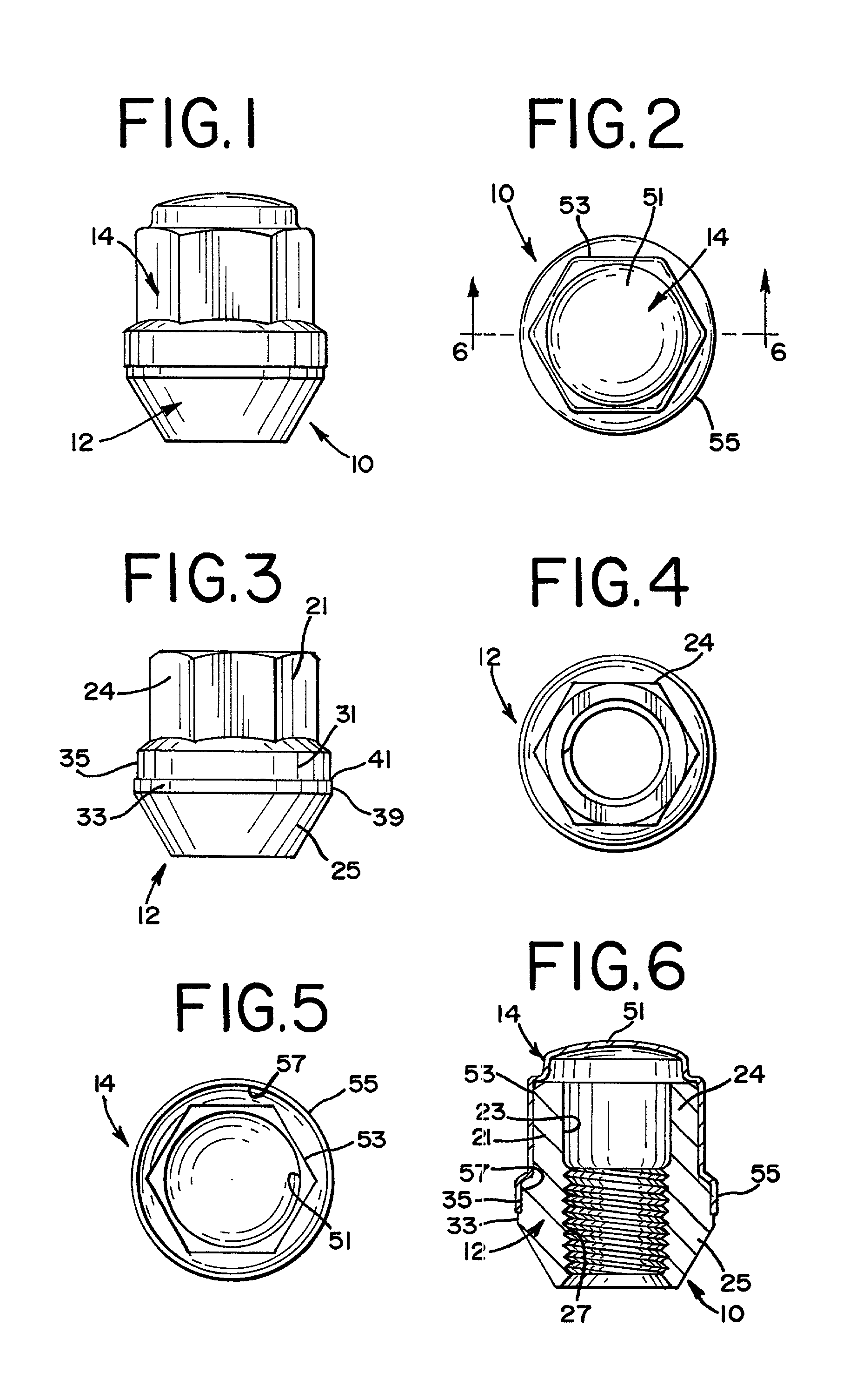
[0028]Referring now to the drawings, and particularly to FIGS. 1–6, a decorative capped wheel nut assembly comprising the present invention is seen generally at 10. The wheel nut assembly 10 includes a nut insert 12 and a decorative cap 14 fastened securely together by a method embodying features of the invention.

[0029]FIGS. 1, 2 and 6 illustrate the wheel nut 10 assembly, i.e., an assembled nut insert 12 and cap 14. FIGS. 3 and 4 illustrate a nut insert 12 separately. FIG. 5 illustrates a cap 14 separately (end view).

[0030]As seen in FIGS. 3, 4 and 6, the nut insert 12 comprises a body 21 having a cylindrical bore 23 extending axially through it from a hex-shaped section 24 on one end to a frusto-conical base 25 on the other. The nut insert 12 is commonly referred to as a hex-nut insert and is fabricated in a conventional manner of carbon steel. The frusto-conical base 25 is adapted to seat in a conventional manner in a wheel rim aperture (not shown) to fasten the wheel rim to a ve...

second embodiment

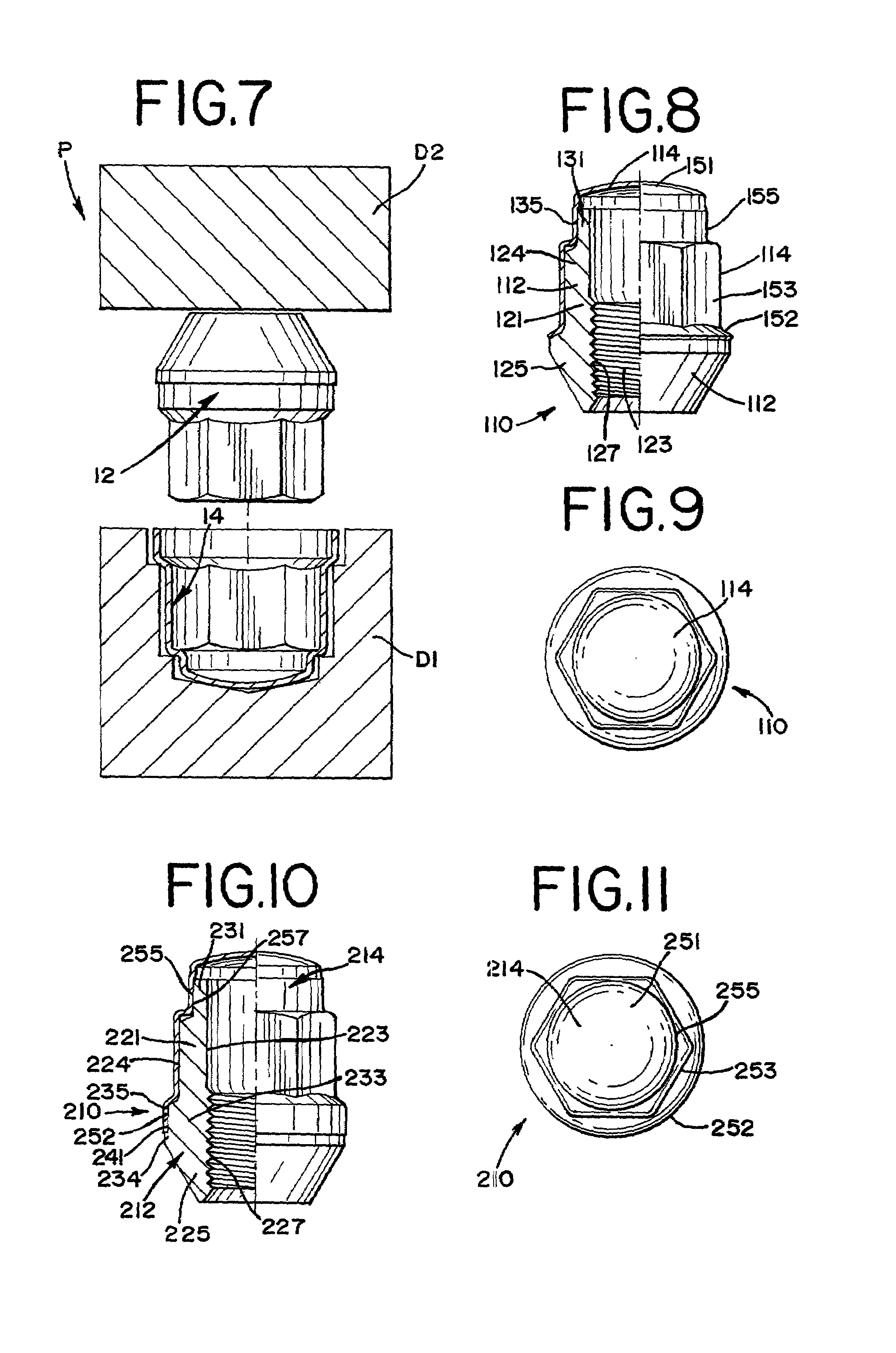
[0036]Referring now to FIGS. 8 and 9, a decorative capped wheel nut assembly comprising the invention is seen generally at 110. The assembly 110 includes a nut insert 112 and a decorative cap 114 fastened together according to the present invention.

[0037]The nut insert 112 comprises a body 121 having a cylindrical bore 123 extending axially through it from a cylindrical section 131 on one end to a frusto-conical base 125 on the other. The base 125 is adapted to seat in a wheel rim aperture (not shown). The bore 123 is internally threaded at 127. The insert 112 is coated in a manner previously discussed.

[0038]Between the conical base 125 and the cylindrical section 131, there is a hex-shaped section 124. The hex-shaped section 124 corresponds to the hex section 24 in the insert body 21 of the assembly 10.

[0039]The axially outer, or end cylindrical section 131, has a coated cylindrical outer surface 135 with an OD of 0.660 inches. The surface 135 has an axial length of 0.190 inches.

[0...

third embodiment

[0042]Referring now to FIGS. 10 and 11, a decorative capped wheel nut assembly comprising the invention is seen generally at 210. The assembly 210 includes a nut insert 212 and a decorative cap 214 fastened together according to the invention.

[0043]The nut insert 212 comprises a body 221 having a cylindrical bore 223 extending axially through it from a cylindrical section 231 on one end to a frusto-conical base 225 on the other. The base 225 is adapted to seat in a wheel rim aperture (not shown). The bore 223 is internally threaded at 227. Like the inserts 12 and 112, the insert 212 is coated.

[0044]Between the conical base 225 and the cylindrical section 231 there is a hex-shaped section 224. The hex-shaped section 224 corresponds to the section 24 in the insert body 21 of the insert 24.

[0045]Between the hex-shaped section 224 and the frusto-conical base 225, the insert body 221 has two cylindrical body sections 233 and 234. The axially outer cylindrical section 233 of the illustrat...


PUM


Abstract

A decorative cap and wheel nut or bolt insert, and a method of assembling them. The insert is coated and/or plated and includes a hex-shaped section and a section having a circular cylindrical outer surface. A cap includes a hex cross-section segment and a circular cylindrical cross-section segment. The hex cross-section segment of the cap slips easily over the hex section of the insert while the circular cylindrical cross-section segment has a smaller ID than the OD of the circular cylindrical insert section whereby an interference fit is formed between them when the insert is press fit into the cap.

Description

FIELD OF THE INVENTION[0001]This invention relates generally to wheel nuts or bolts for securing a vehicle wheel, i.e., a tire and rim, on a motor vehicle. It relates particularly to a decorative capped wheel nut or bolt and a method of assembly.BACKGROUND OF THE INVENTION[0002]Decorative capped wheel nuts and bolts are well-known in the automotive art. A decorative capped wheel nut, for example, conventionally comprises a nut insert and a decorative cap which is fastened to the insert by welding, crimping or with an adhesive. Examples of these constructions are illustrated in various prior art patents, including the Toth U.S. Pat. No. 4,955,773, the Bydalek U.S. Pat. No. 5,772,377, the Chaivre U.S. Pat. Nos. 4,018,133, and 4,056,862, the Baltzell U.S. Pat. No. 4,764,070 and the Somers et al. U.S. Pat. No. 6,036,420, for example. It is also known to form threads in a cap and in a lug nut and thread the cap onto the nut. See the Nolan et al. U.S. Pat. No. 5,180,266 in this regard.[00...

Claims


Application Information

Patent Timeline
IPC IPC(8): F16B37/14F16B37/00F16B4/00
CPCF16B37/14F16B4/004
Inventor WILSON, LARRY J.
Owner INDAL & AUTOMOTIVE FASTENERS L L C
Why Eureka
Try Eureka