Phase center measurement of electronic warfare antennas using GPS signals

a technology of electronic warfare and phase center measurement, applied in the direction of measurement devices, communication jamming, instruments, etc., can solve the problems of enormous error in the determination of the location of the emitter, and the procedure can also encounter measurement errors, and achieve the effect of accurate measuremen

Inactive Publication Date: 2005-11-22
THE UNITED STATES OF AMERICA AS REPRESETNED BY THE SEC OF THE AIR FORCE
View PDF19 Cites 7 Cited by
  • Summary
  • Abstract
  • Description
  • Claims
  • Application Information

AI Technical Summary

Benefits of technology

[0008]The present invention provides a procedure and an apparatus enabling accurate measuring of distances and angles between a movable platform such as an aircraft and a distant signal source such as a ground-located electromagnetic source.

Problems solved by technology

If the vectors connecting the receiving antennas are determined with errors, these errors can cause enormous emitter location determination errors.
In addition to the added complexity of supplying, mounting and measuring associated with the added global position system antennas used in this present state of the electronic warfare art, this procedure can also encounter measurement error as a result of the phase center or the electrical center of the electronic warfare antenna being located in a position differing significantly from the physical center of the antenna.

Method used


Image

  • Phase center measurement of electronic warfare antennas using GPS signals
  • Phase center measurement of electronic warfare antennas using GPS signals
  • Phase center measurement of electronic warfare antennas using GPS signals

Examples


Embodiment Construction

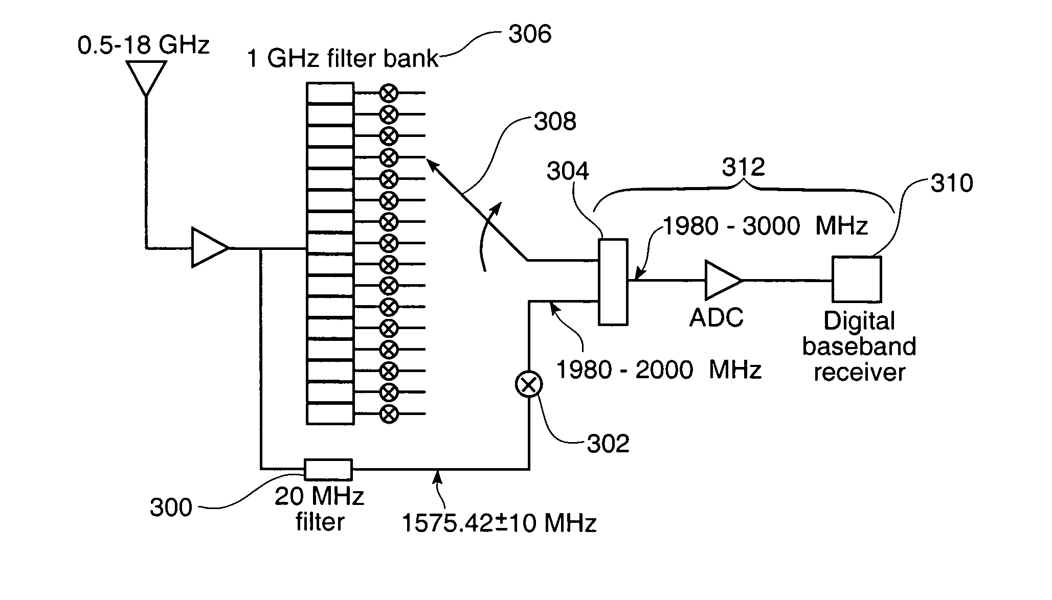
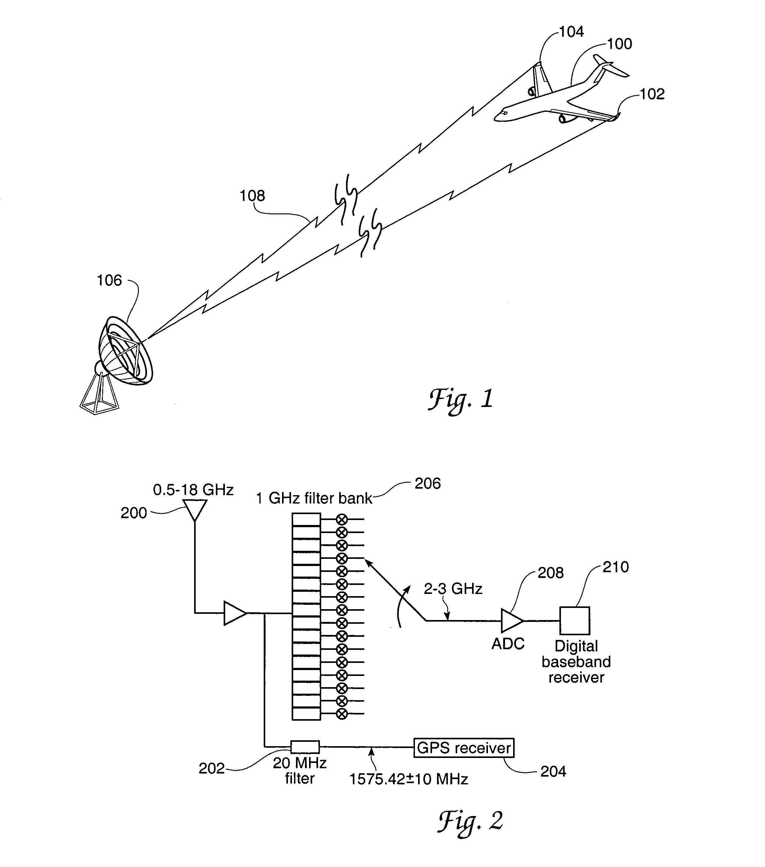
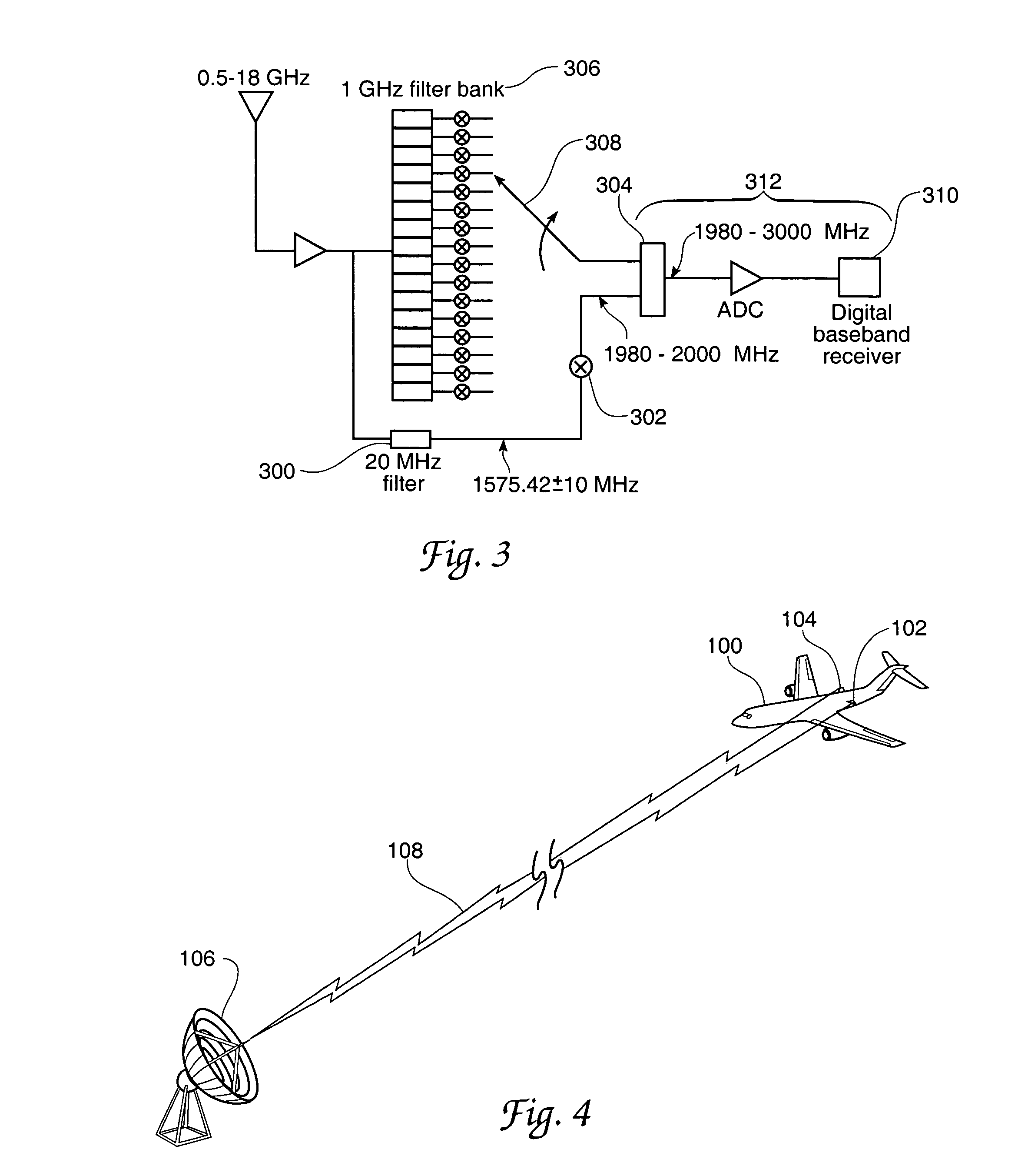
[0030]In the above identified patent document “GPS RECEIVER WITH ELECTRONIC WARFARE RECEIVER FONT END” two of the inventors named in the present patent document and a third colleague have disclosed an invention in which certain functions of an electronic warfare radio receiver and a global position system radio receiver are advantageously combined. The present invention enlarges upon the concept of this receiver combination and provides specific use details for the combination receiver in solving a frequent electronic warfare signal-locating problem. The “GPS RECEIVER WITH ELECTRONIC WARFARE RECEIVER FONT END” document has been incorporated by reference herein in the material above.

[0031]Generally the underlying concept for the present invention may be stated in simple terms. In lieu of the presently practiced procedure wherein a global position system antenna is disposed adjacent an electronic warfare antenna for antenna dimensional and location calibration purposes we find it is p...


PUM


Abstract

An electronic warfare apparatus for determining the location of for example a ground based source of electromagnetic radiation from a platform such as an aircraft. Location is determined using angle of arrival based vector determinations provided by signal differences detected in the ground based signals arriving at platform antennas. Elimination of angle of arrival errors arising from imprecise knowledge of platform electronic warfare antenna characteristics is a focal point of the invention and is accomplished through precision use of global position system information received via the same electronic warfare antennas. Accurate determination of electronic warfare antenna characteristics prior to consideration of the large distance multiplication factors imposed by aircraft to distant signal source geometry enables accurate distant signal source location using the invention.

Description

RIGHTS OF THE GOVERNMENT[0001]The invention described herein may be manufactured and used by or for the Government of the United States for all governmental purposes without the payment of any royalty.CROSS REFERENCE TO RELATED PATENT DOCUMENT[0002]The present document is somewhat related to the co pending and commonly assigned patent application document “GPS RECEIVER WITH ELECTRONIC WARFARE RECEIVER FRONT END”, Ser. No. 10 / 815,600 filed of even date herewith. The contents of this related even filing date application are hereby incorporated by reference herein.BACKGROUND OF THE INVENTION[0003]In many electronic warfare applications, it is desirable determine the location of a certain distantly located signal emitter. Such a determination may be made in relative terms with respect to a known reference position and may also be transferred from this relative position to a fixed or global position with the aid of additional processing. In making such position determinations, the angle ...

Claims


Application Information

Patent Timeline
Patent Type & Authority Patents(United States)
IPC IPC(8): G01S13/00G01S13/06G01S5/02G01S11/04G01S19/10G01S19/21G01S19/46
CPCG01S5/0252G01S11/04
Inventor LIN, DAVID M.TSUI, JAMES B. Y.
Owner THE UNITED STATES OF AMERICA AS REPRESETNED BY THE SEC OF THE AIR FORCE
Why Eureka
Try Eureka