Milling cutter

a cutter and cutter body technology, applied in the field of metal cutting tools, can solve problems such as the inability to face mill

Inactive Publication Date: 2005-12-20
KENNAMETAL INC
View PDF13 Cites 34 Cited by
  • Summary
  • Abstract
  • Description
  • Claims
  • Application Information

AI Technical Summary

Benefits of technology

[0009]Briefly, the present invention relates to a cutting tool for cutting a workpiece. The cutting tool includes a tool body having an outer surface thereon and a central axis therein and at least a first and second spiraling flute in the outer surface. Each flute includes a plurality of inserts secured therein to define an axial rake angle, wherein the axial rake angle of the inserts varies between flutes and within each flute.

Problems solved by technology

One of the disadvantages of such design is that the lead insert in at least one helix must either be of a different length or offset inward and thus incapable of face milling.
Consequently, all of the inserts are generally not the same and thus not interchangeable, thus requiring the manufacture and inventory of multiple inserts.

Method used


Image

  • Milling cutter
  • Milling cutter
  • Milling cutter

Examples


Embodiment Construction

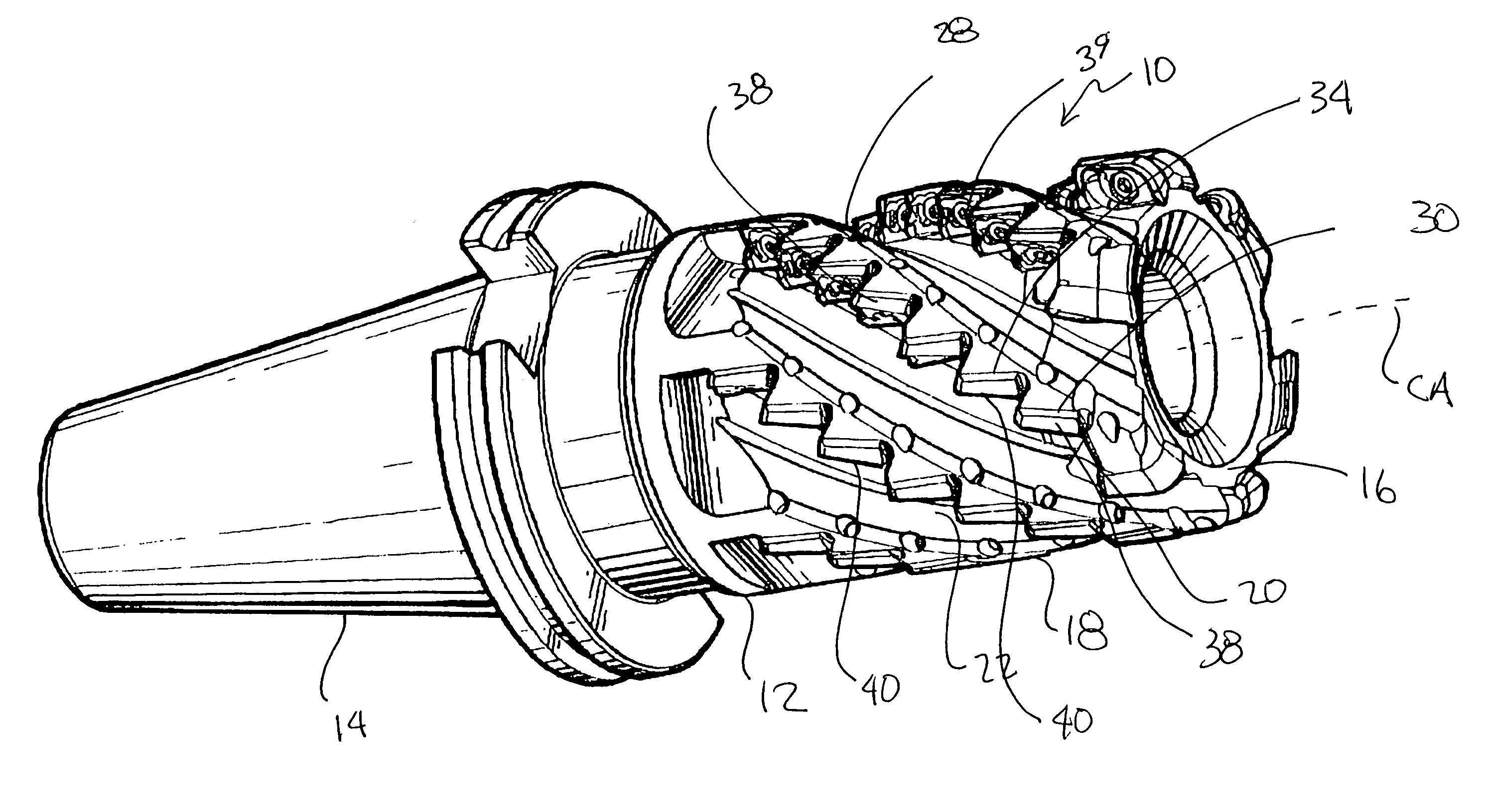
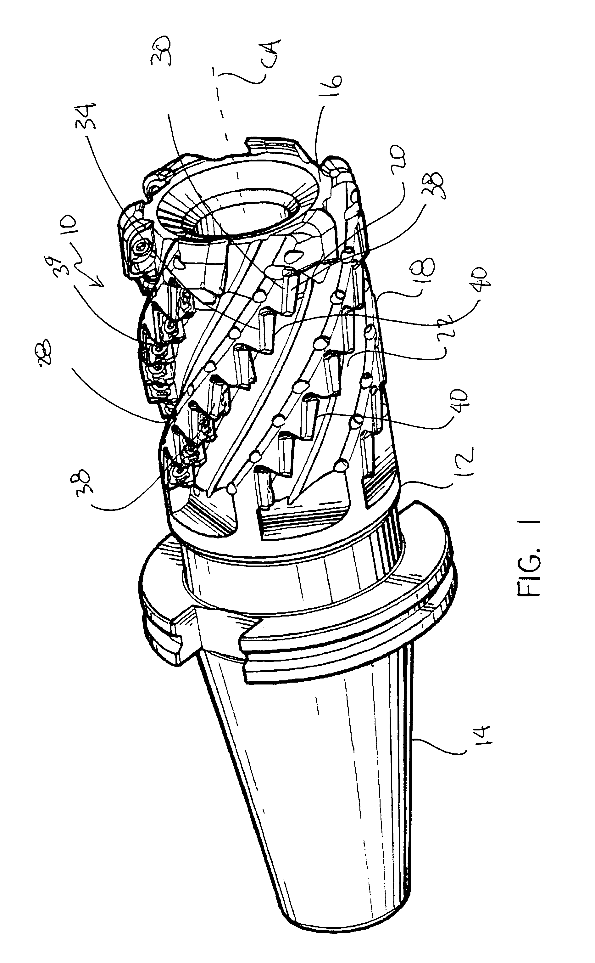
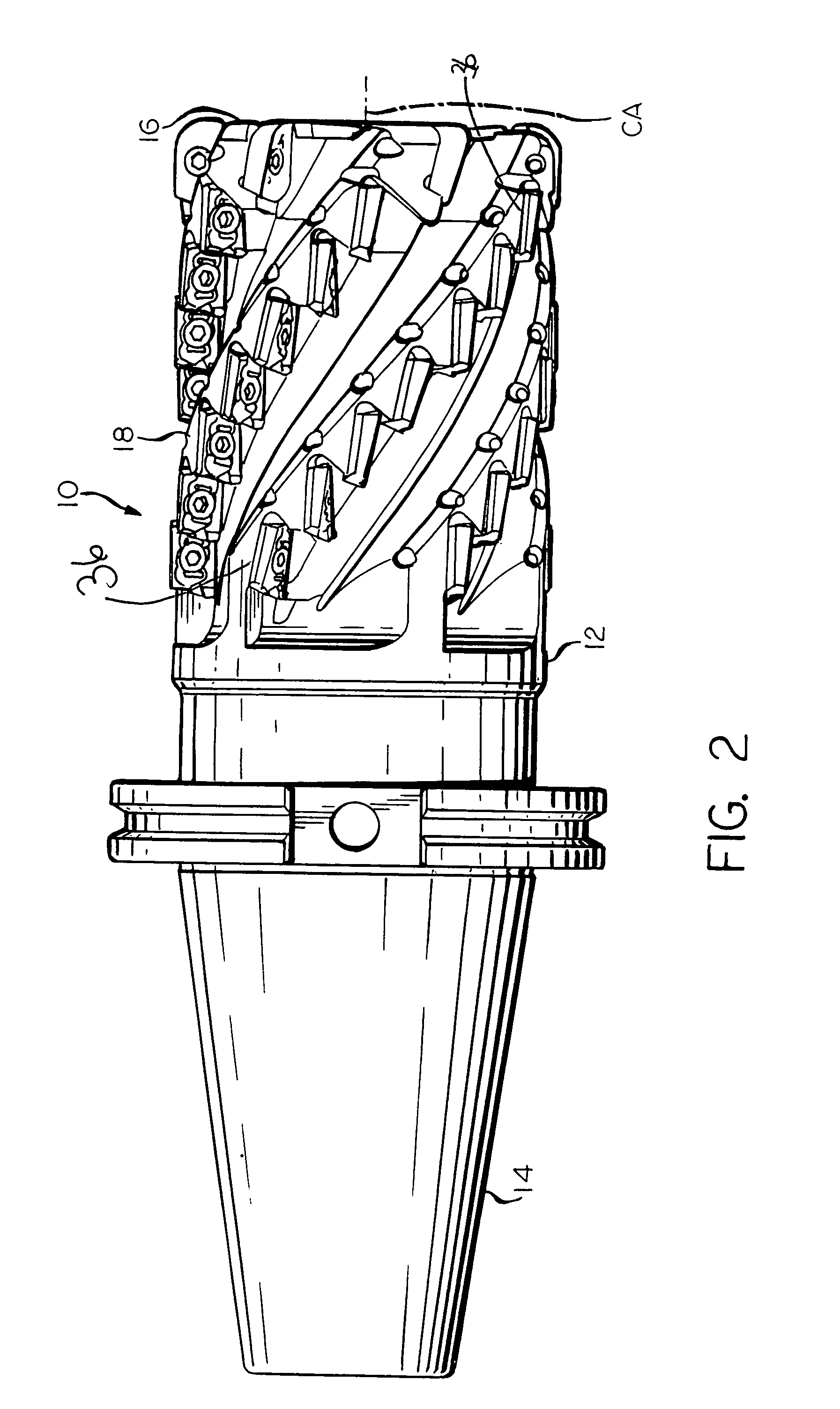
[0016]Referring to the drawings wherein like reference characters designate like elements there is shown a helical cutting tool 10, such as an end mill, face mill, or any other known mill. It will be appreciated that although the invention is described in relation to a multiple fluted helical end mill, the inventive concept of differing rake angles both along a single flute and between two or more flutes is applicable to most any suitable cutting tool.

[0017]As shown in FIG. 1, the helical end mill 10 includes a tool body 12 and a shank 14. The shank 14 is configured so as to be capable of insertion and securing within a spindle of a milling or other cutting machine (not shown) as is well known in the art. The shank 14 may be of any shape or design so as to be capable of this insertion and securing. Such designs include, but are not limited to, V-flange, taper, shell mill mount, and Weldon shank. Obviously, should the mill instead be a face mill, then no shank exists as is well known...


PUM


Abstract

A cutting tool for cutting a workpiece comprising a tool body having an outer surface thereon and a central axis therein and including at least a first and second spiraling flute in the outer surface, each flute including a plurality of inserts secured therein to define an axial rake angle, wherein the axial rake angle of the inserts varies between flutes and within each flute.

Description

FIELD OF THE INVENTION[0001]The present invention relates generally to metal cutting tools and more particularly to helical cutting tools such as end mills and face mills. Specifically, the present invention relates to a milling cutter including multiple flutes having inserts wherein the axial rake angle of the inserts varies between each flute and within each flute.BACKGROUND OF THE INVENTION[0002]Helical end mills and face mills are well known in the industry. Conventional helical end mills include those shown on pages 182–216 in Kennametal's Milling Catalog No. 5040, copyright 1995.[0003]One form of helical mill that has been in use for years is a helical mill where the cutting edge of each insert is axially spaced apart from the cutting edge of the next adjacent insert and where the inserts in each helix are staggered such that two or more rows are necessary to produce one complete or “all effective” cutting edge. Such a design is shown by the Kennametal 0 degree Lead—Helical En...

Claims


Application Information

Patent Timeline
Patent Type & Authority Patents(United States)
IPC IPC(8): B23C5/10
CPCB23C5/109Y10T407/1952Y10T407/1966
Inventor DEROCHE, KENNETH G.FRYE, HOWARD W.DUDZINSKY, RONALD L.FRANCIS, MARK A.
Owner KENNAMETAL INC
Why Eureka
Try Eureka