

Analog-to-digital converter and method of analog-to-digital conversion
a technology of analog-to-digital converter and conversion method, applied in analogue/digital conversion, transmission systems, instruments, etc., can solve problems such as the binary digital data s
- Summary
- Abstract
- Description
- Claims
- Application Information
AI Technical Summary
Benefits of technology
Problems solved by technology
Method used
Image

Examples
first embodiment
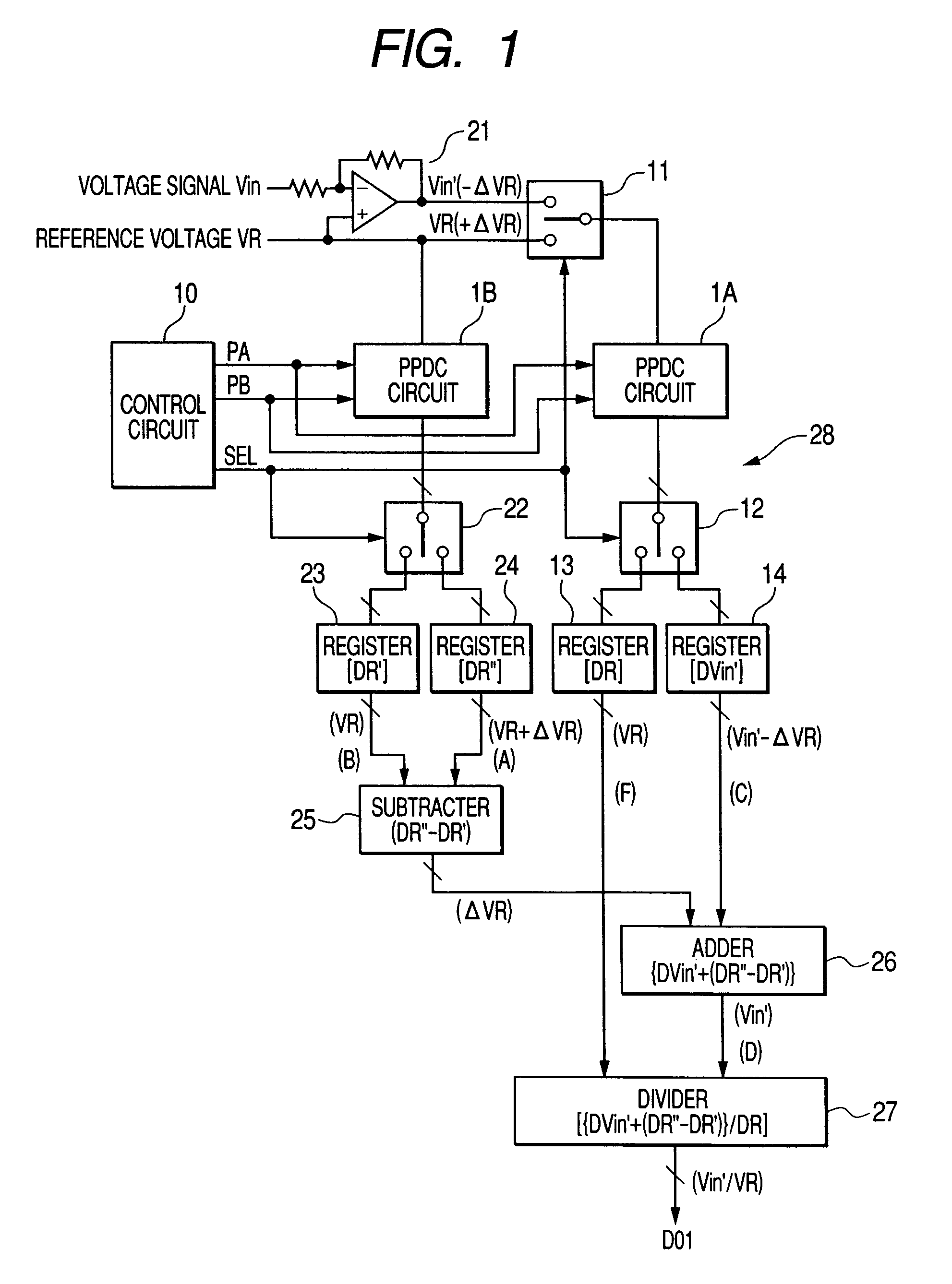
[0056]FIG. 1 is a block diagram showing a structure of an A / D converter according to a first embodiment of the invention. As shown in FIG. 1, this A / D converter 28 includes a PPDC (Pulse-Phase-Difference Coding) circuit 1A, a PPDC circuit 1B, a control circuit 10, an inverting amplifier 21, an input-selection switch 11, output selection switches 12, 22, registers 13, 14, 23, 24, a subtracter 25, an adder 26, and a divider 27. The PPDC circuits 1A and 1B have the same structure and operate in a like manner as the PPDC circuit 1 shown in FIG. 19.
[0057]The analog voltage signal Vin is amplified by the inverting amplifier 21 and then outputted to the input selection switch 11 as an analog voltage signal Vin′. The gain of the inverting amplifier 21 is one. The input selection switch 11 selects one of the analog voltage signal Vin′ and the reference voltage VR in accordance with a selection signal SEL received from the control circuit 10, and supplies it to the PPDC circuit 1A, The refere...
second embodiment
[0070]FIG. 4 is a block diagram showing a structure of an A / D converter 33 according to a second embodiment of the invention. In FIG. 4, elements that are the same as those shown in FIG. 1 are given the same reference characters, and explanation thereof will be omitted. The second embodiment is different from the first embodiment in that the second embodiment uses a non-inverting amplifier 31 and a subtracter 32 (variation compensation circuit) instead of the inverting amplifier 21 and the adder 26.
[0071]The operation of the A / D converter 33 according to the second embodiment of the invention is explained below. Assume that the reference voltage VR has increased larger by +ΔVR since the time when the PPDC circuit 1A performed A / D conversion on the reference voltage VR, so that the value of the analog voltage signal Vin′ presently received by the PPDC circuit 1A is represented by (Vin+ΔVR) (see FIG. 5).
[0072]In this case, the subtracter 32 outputs, as a subtraction result, a data set...
third embodiment
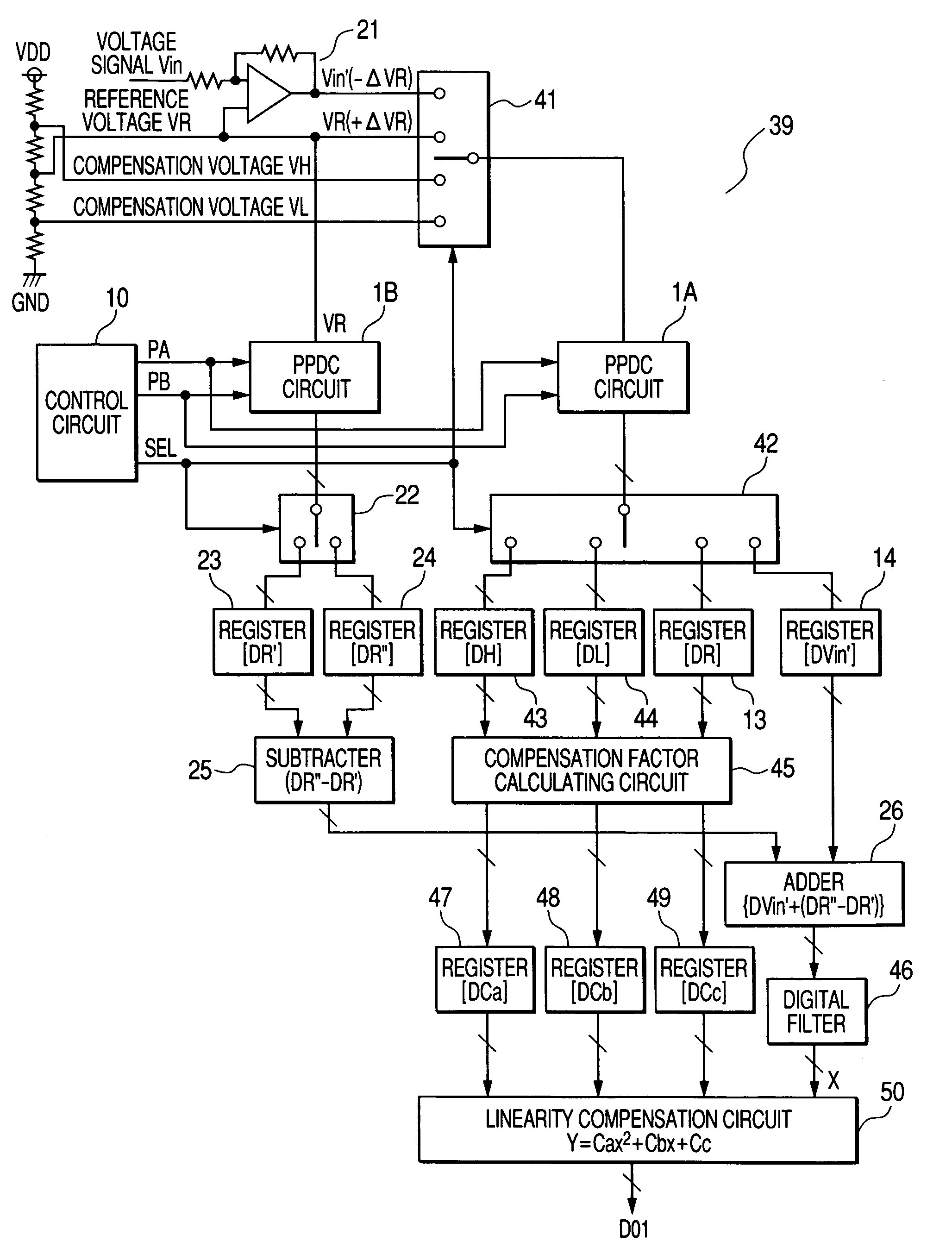
[0073]FIG. 6 is a block diagram showing a structure of an A / D converter 35 according to a third embodiment of the invention. The third embodiment is different from the first embodiment in that the registers 14, 24 are eliminated, and the subtracter 25 and the adder 26 are replaced by a subtraction / addition device (variation compensation circuit) 34.
[0074]In the third embodiment, the data set DR and the data set DR′ A / D-converted by the PPDC circuit 1A and the PPDC circuit 1B, respectively, are stored in the register 13 and 23, respectively, as with the case of the first embodiment. However, the data set representing the value of (Vin′−ΔVR) A / D-converted by the PPDC circuit 1A, and the data set representing the value of (VR) or (VR+ΔVR) A / D-converted by the PPDC circuit 1B are directly sent to the subtraction / addition device 34. Accordingly, the third embodiment can be made simpler than the first embodiment in structure.
PUM
 Abstract
Description
Claims
Application Information