Al technical title is built by PatSnap Al team. It summarizes the technical point description of the patent document.
a compressed image and enhanced technology, applied in image enhancement, instruments, television systems, etc., can solve the problems of degrading image data, complex reproduction, and often unwishful exact copying, and achieve enhanced decompressed image data and input digital image data.
Active Publication Date: 2006-04-18
XEROX CORP
View PDF4 Cites 22 Cited by
Summary
Abstract
Description
Claims
Application Information
AI Technical Summary
This helps you quickly interpret patents by identifying the three key elements:
Problems solved by technology
Method used
Benefits of technology
[0013]In accordance with another embodiment of the present invention, an image processing method includes receiving wavelet domain data defining a digital image where the wavelet domain data includes N levels of decomposition. M levels, where M is less than N, are then input into an automated image enhancement system which derives at least one of a tone reproduction curve and a sharpness filter for enhancement of the input digital image data. The image data is more completely decompressed, either concurrently or at a later time, to obtain decompressed image data representing the digital image at a selected level of decomposition. Using either or both of the final reproduction curve or sharpness filter, the decompressed image data is enhanced.
Problems solved by technology
However, as customers have become more sophisticated in their document reproduction requirements, they have recognized that an exact copy is often not desired.
With photographs, in particular, reproduction is complicated given the inexact nature of the discipline, variations in equipment, aging of photographs, and the like.
This is undesirable in that the decompression operation slows the overall enhancement operation, the image processing apparatus must be provided with additional memory to accommodate large amounts of uncompressed image data, and each compression operation itself, further degrades the image data due to data loss.
Method used
Image
Click on the blue label to locate the original text in one second.
Reading with bidirectional positioning of images and text.
Examples
Embodiment Construction
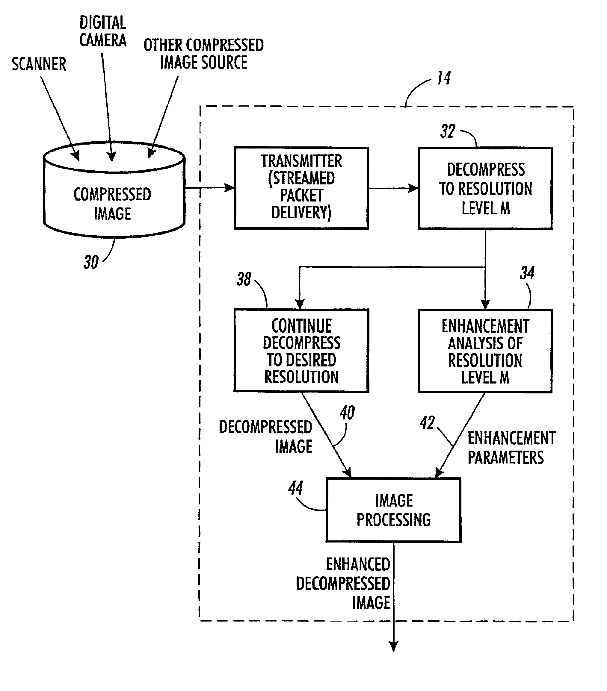
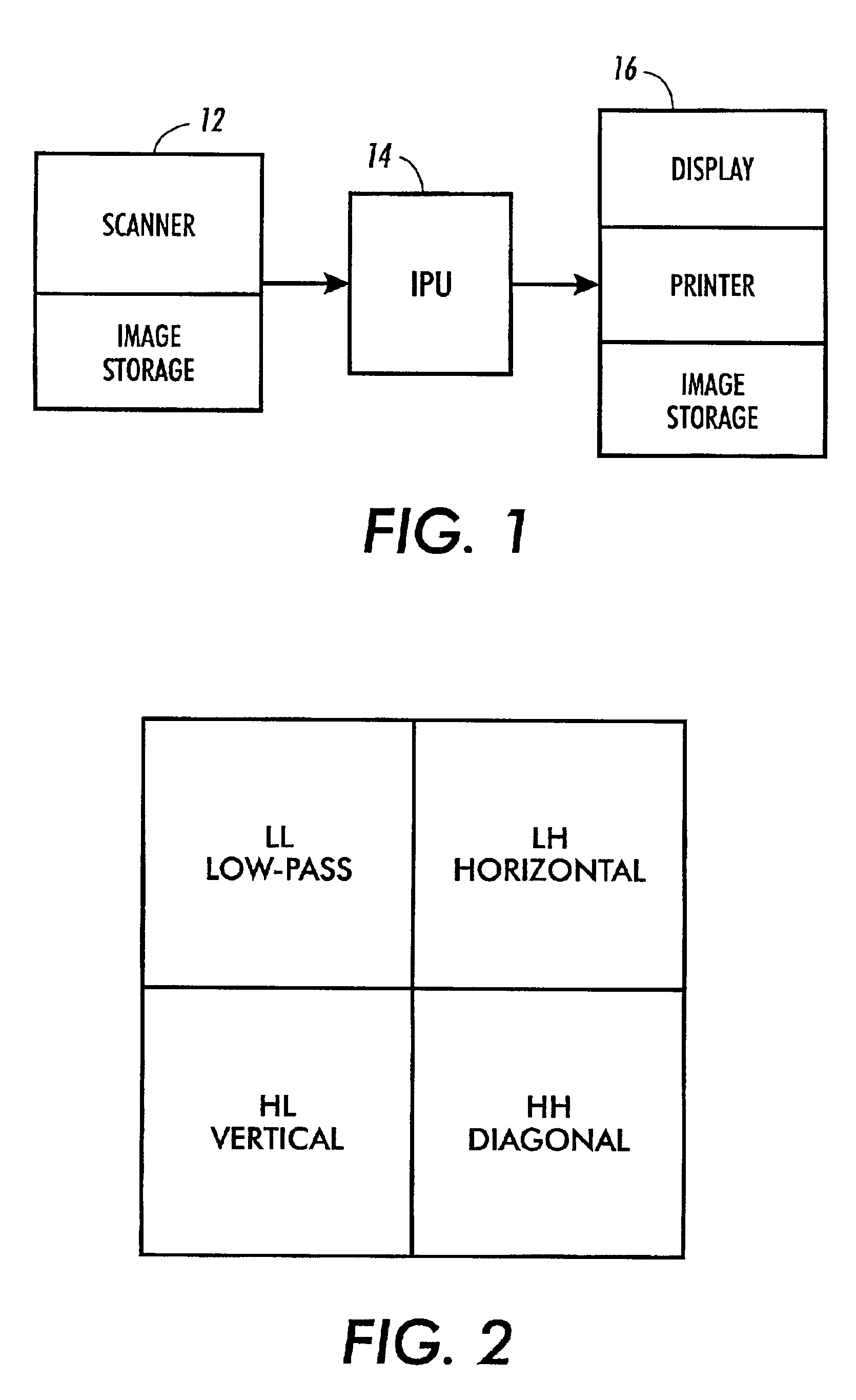
[0035]Referring now to the drawings wherein the showings are for purposes of illustrating a preferred embodiment of the invention only and not for limiting the invention in any way, FIG. 1 diagrammatically illustrates an image processing apparatus including an image input terminal 12, an image processing unit (IPU) 14, and an image output terminal 16. The input terminal 12 can be any source of digital image data including a scanner, digital camera, or a source of stored image data. The image processing unit 14 is provided by any suitable electronic computing apparatus including a microprocessor or the like for carrying out digital image processing as described herein. Image data from the input terminal 12 are supplied to the IPU 14 for processing. After processing the data, the IPU 14 outputs the processed data to the image output terminal 16 which can include a non-impact printer, video display, image storage device or the like.
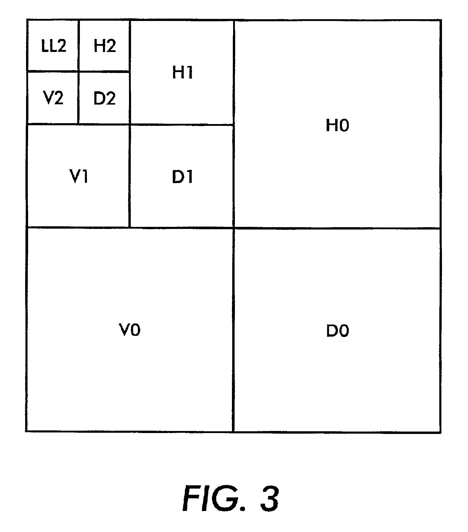
[0036]The decomposition of a digital image into differ...
PUM
Abstract
A xerographic apparatus, a printer, a printer server, and the like processes wavelet domain image data and includes means for receiving the wavelet domain image data representative of an input digital image. The wavelet domain image data may be formatted as a JPEG 2000 compressed file or other wavelet domain file including N levels of wavelet decompositions. An M-level extractor extracts an Mth level wavelet decomposition from the wavelet domain image data where M is <N. The extracted Mth level wavelet decomposition is a low resolution representation of the input digital image. An image enhancement system receives the extracted Mth level wavelet decomposition and derives an enhancement process such as a tone reproduction curve, a sharpness filter, and the like from the extracted Mth level wavelet decomposition. The enhancement process is used to enhance a higher resolution representation of the digital input image.
Description
CROSS REFERENCE TO RELATED U.S. PATENTS[0001]Cross reference is made to the following commonly assigned U.S. Patents or applications to Eschbach et al., each of which is hereby expressly incorporated by reference herein: U.S. Pat. Nos. 5,414,538; 5,357,352; 5,450,502; 5,371,615; 5,363,209; 5,450,217; and, 5,802,214 and Ser. No. 09 / 448,947. Similarly, commonly assigned U.S. Pat. No. 5,347,374 to Fuss et al. is also hereby expressly incorporated by reference herein.BACKGROUND OF THE INVENTION[0002]In the past, a typical application for copiers or scan-to-print image processing systems was to reproduce an input image as accurately as possible, i.e., render a copy. Thus, copies have been rendered as accurately as possible, including flaws in the source image. However, as customers have become more sophisticated in their document reproduction requirements, they have recognized that an exact copy is often not desired. Instead, an inexact copy that is perceived as a higher quality image ha...
Claims
Application Information
Patent Timeline
Application Date:The date an application was filed.
Publication Date:The date a patent or application was officially published.
First Publication Date:The earliest publication date of a patent with the same application number.
Issue Date:Publication date of the patent grant document.
PCT Entry Date:The Entry date of PCT National Phase.
Estimated Expiry Date:The statutory expiry date of a patent right according to the Patent Law, and it is the longest term of protection that the patent right can achieve without the termination of the patent right due to other reasons(Term extension factor has been taken into account ).
Invalid Date:Actual expiry date is based on effective date or publication date of legal transaction data of invalid patent.