Pressing iron having a soleplate of special form

a pressing iron and soleplate technology, applied in the field of pressing irons, can solve problems such as wrinkles on the rear edge of the flat iron, and achieve the effects of reducing the risk of wrinkles during ironing, reducing the risk of wrinkles, and improving efficiency

Inactive Publication Date: 2006-07-25
SEB SA
View PDF8 Cites 1 Cited by
  • Summary
  • Abstract
  • Description
  • Claims
  • Application Information

AI Technical Summary

Benefits of technology

[0009]Such a soleplate has the advantage of possessing three different points that can be utilized differently by the user during ironing of precise forms.
[0010]Such a soleplate presents equally the advantage of having a leading edge in the form of a convex curve that permits the ironing of large surfaces, by a rapid sweeping of the arm, without producing wrinkles. In effect, it is important, to minimize the risk of formation of wrinkles during ironing, that the leading edge of the soleplate not be perpendicular to the direction of displacement of the iron. The convex form of the edge of the soleplate satisfies this requirement perfectly.
[0011]Finally, the substantially straight edges of the iron will naturally be utilized to follow the straight edges of the clothing, such as the edges of shirt sleeves or the legs of trousers, in a manner to assure in these zones a greater ironing length and thus a better efficiency.

Problems solved by technology

Such a soleplate form has, however, the drawback of allowing ironing only in one preferential direction, from the back toward the front, the flat rear edge tending to form wrinkles when the iron is displaced from the front toward the back.
However, the forms of soleplates disclosed in these documents present the drawback of having two identical end points and thus of offering the user only a single form of point to assure the various ironing tasks.
However, such a soleplate presents only two points of different forms and does not possess an optimized form presenting a plurality of work zones of different forms to be best adapted to the different forms of the pieces to be ironed.

Method used


Image

  • Pressing iron having a soleplate of special form
  • Pressing iron having a soleplate of special form

Examples


Embodiment Construction

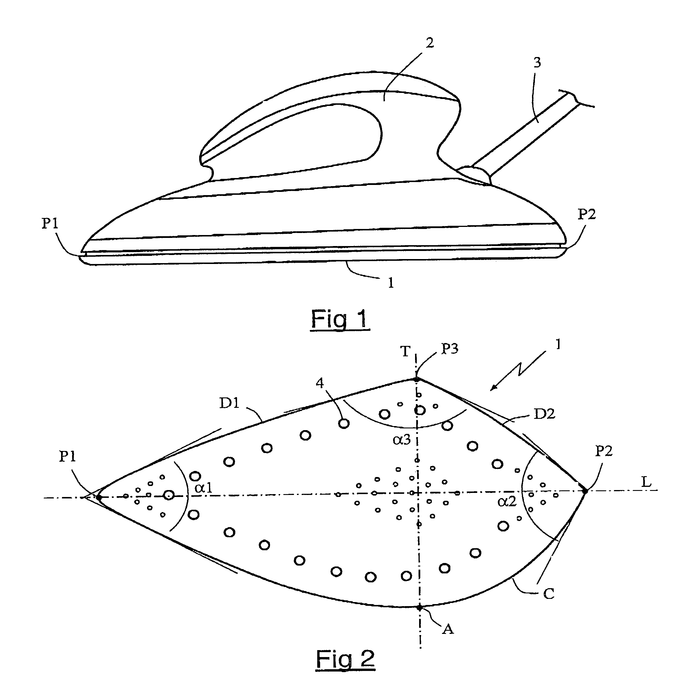
[0020]FIG. 1 shows a steam pressing iron having a heating soleplate 1, a handle 2 and an electric supply cord 3. Handle 2 presents an ergonomic form permitting gripping of the iron according to different directions with great ease. The iron is equipped with a steam chamber, not shown, and soleplate 1, represented in greater detail in FIG. 2, has openings 4 for the release of steam.

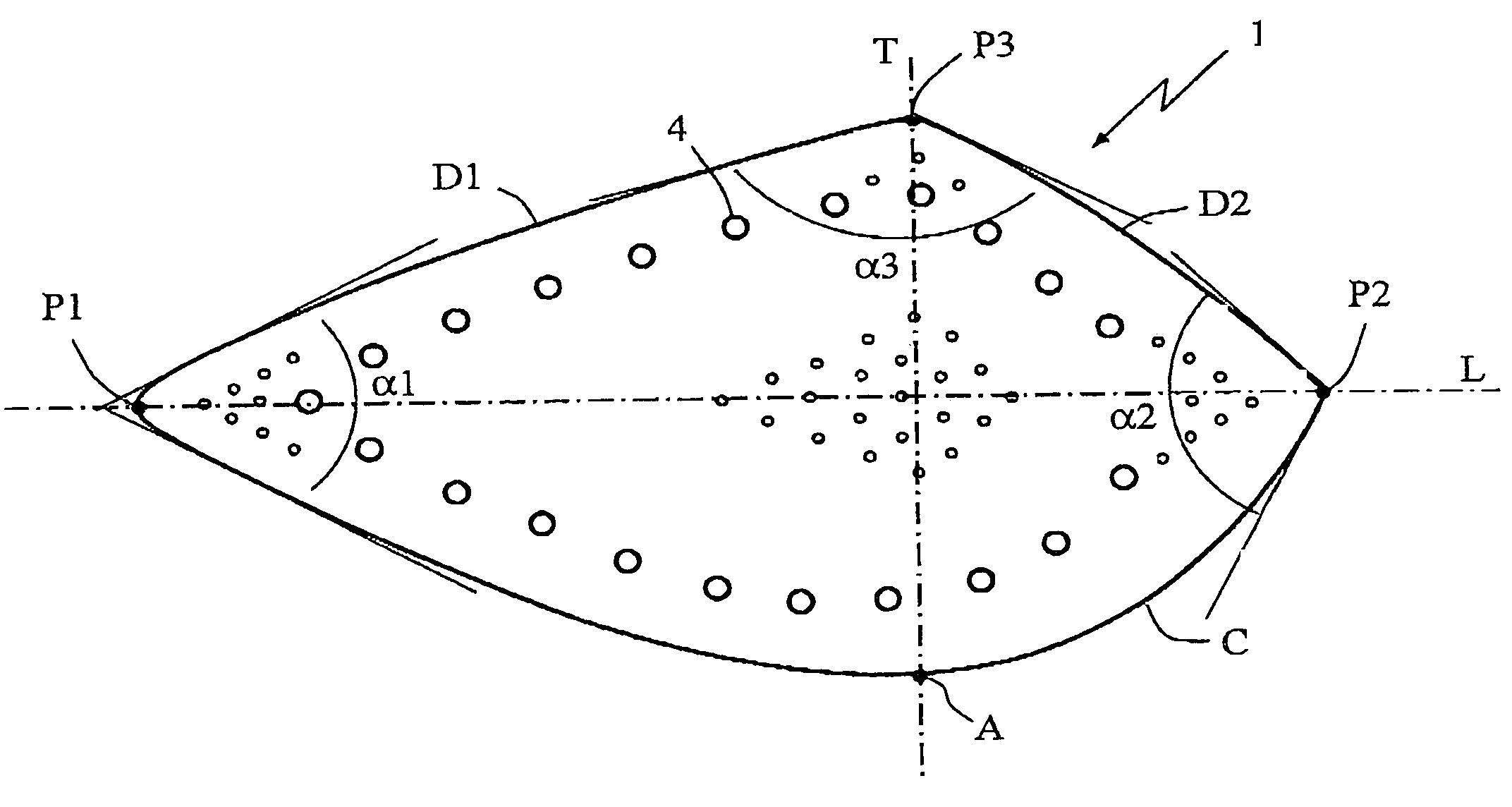
[0021]According to a particular embodiment of the pressing iron according to the iron, soleplate 1 has a special form with three points P1, P2, P3, the end points P1 and P2 being disposed on the longitudinal axis L of the iron and the third point P3 being substantially offset with respect to longitudinal axis L.

[0022]Soleplate 1 has, at one side of longitudinal axis L, substantially straight edges D1 and D2 extending respectively between the points P1 and P3 and between the points P3 and P2. Soleplate 1 has, at the other side of longitudinal axis L, a highly curved edge C connecting points P1 and P2, the f...


PUM


Abstract

Pressing iron having a soleplate (1) presenting an ironing surface and a periphery having three vertices (P1, P2, P3) presenting different angles. Two of the vertices (P1, P2) of the soleplate are, on the one hand, connected together by a convex curve delimiting one edge (C) of the soleplate (1) and, on the other hand, are connected to the third point (P3) by substantially straight or slightly convex curves delimiting other edges (D1, D2) of the soleplate (1).

Description

BACKGROUND OF THE INVENTION[0001]The present invention relates to a pressing iron and more particularly to a pressing iron having a soleplate of special form.[0002]Most pressing irons have a soleplate presenting a point at the front end of the iron, a wide and flat rear edge, and slightly convex lateral edges starting from the ends of the rear edge toward the front point. Such a soleplate form has, however, the drawback of allowing ironing only in one preferential direction, from the back toward the front, the flat rear edge tending to form wrinkles when the iron is displaced from the front toward the back.[0003]There are known, from documents FR 1 341 921 and GB 1 399 826, pressing irons having a soleplate provided with a point at each of the longitudinal ends of the iron. Such irons have the advantage of offering the same ease of ironing from front to back and from back to front. However, the forms of soleplates disclosed in these documents present the drawback of having two ident...

Claims


Application Information

Patent Timeline
Patent Type & Authority Patents(United States)
IPC IPC(8): D06F75/38D06F75/30
CPCD06F75/38D06F75/30
Inventor GELUS, DOMINIQUEHIPP, EDGARRENAULT, FABRICE
Owner SEB SA
Why Eureka
Try Eureka