Annuloplasty band and method

a technology of annuloplasty and band, which is applied in the field of devices and methods for repair of heart valves, can solve the problems of distortion of the normal shape of the valve orifice, left ventricular outflow obstruction, and both valves can be subjected to or incur damage, and achieve the effects of convenient passage of sutures through the eyelets, convenient implanting, and accurate evaluation of the valve annulus

Inactive Publication Date: 2005-10-18
MEDTRONIC INC
View PDF62 Cites 241 Cited by
  • Summary
  • Abstract
  • Description
  • Claims
  • Application Information

AI Technical Summary

Benefits of technology

[0011]One aspect of the present invention relates to an annuloplasty band that is readily implanted to repair an atrio-ventricular heart valve, such as the mitral or tricuspid valve, and which may readily be secured (e.g., sutured) to the valve annulus tissue, for example to the antero-lateral and / or postero-medial trigones of a mitral valve. Another aspect of the present invention relates to methods of implantation of annuloplasty bands, for example, by suturing through eyelets adjacent the ends of the band to the valve annulus tissue. This provides an annuloplasty band that is anchored into the fibrous tissue of the valve (for example, in one embodiment, the antero-lateral and postero-medial trigones), which is believed to provide many of the advantages of annuloplasty rings, without sacrificing the advantages of an annuloplasty band. To this end, yet another aspect of the present invention relates to a holder for selectively maintaining the annuloplasty band during the implant procedure, the holder adapted to facilitate passage of sutures through the eyelets. Yet another aspect of the present invention relates to a sizer adapted to promote accurate evaluation of the valve annulus via sizer cut-out segments and sizer shape, and thus selection of an optimally sized annuloplasty band.
[0016]In a second preferred embodiment of the present invention, the annuloplasty band generally comprises a sheath, and a generally arcuate stiffening element disposed within the sheath. The stiffening element has rounded ends, and the band has a thickness no greater than about 3 mm, preferably no greater than 2.7 mm, and most preferably no greater than 2.5 mm. The low profile annuloplasty band offers less restriction or disturbance to blood flow through the valve. Hence, the minimal cross-section annuloplasty band may reduce stenosis and turbulence, and may minimize the risk of thrombus formation.
[0021]In one preferred embodiment, the above-described method relates to repair of a mitral valve. In this regard, the eyelets are preferably positioned adjacent the antero-lateral trigone and the postero-medial trigone, respectively. The eyelets are then preferably sutured to the valve annulus at the antero-lateral and postero-medial trigones. In an alternative embodiment, the above-described method relates to repair of a tricuspid valve. To this end, the annuloplasty band is positioned to surround the anterior, posterior and a portion of the septal leaflets of the tricuspid valve. The eyelets are sutured to the respective bases of the septal and anterior valve leaflets, adjacent the valve annulus and on either side of the antero-septal commissure to avoid impairment with the cardiac conduction system of the heart.
[0022]In still another preferred embodiment of the invention, a holder is provided in combination with an annuloplasty band. The annuloplasty band is mounted on the holder to help position the annuloplasty band relative to the valve annulus. The holder includes a band-retaining plate forming cut-out areas providing clearance about eyelets formed by the band, thereby promoting placement of sutures through the eyelets.
[0023]Yet another aspect of the present invention relates to a sizer for evaluating a size the valve annulus implant site and indicating which of a number of varying sized annuloplasty bands is best suited for the valve annulus. In a preferred embodiment, a plurality of differently sized sizers are provided, each corresponding in size with an annuloplasty band of the present invention. In this regard, each of the sizers preferably includes markings that identify a potential location of the corresponding annuloplasty band's eyelets were the correspondingly sized band selected for implant. Along these same lines, the sizer delineates a distance between desirable points of the valve annulus. With respect to mitral valve repair procedure, the sizer affords a surgeon the ability to measure an intertrigonal distance and an area of a leaflet of the valve (e.g., anterior leaflet) in order to select an annuloplasty band that most closely matches those parameters.

Problems solved by technology

Both valves can be subjected to or incur damage that requires that the valve(s) be repaired or replaced.
Many of the defects are associated with dilation of the valve annulus.
This dilation not only prevents competence of the valve but also results in distortion of the normal shape of the valve orifice.
A significant surgical diminution of the inter-trigonal distance could cause left ventricular outflow obstruction.
However, it is important not to over restrict the annulus or an unacceptable valvular stenosis could result.
Firstly, by implanting a substantially inexpansible ring (smaller in size than the annulus).
Secondly, by using a contractible ring that may be complicated during implantation.
This type has the disadvantage that the surgeon must then accurately judge not only the ring size to use, but also how to space the implanting sutures in the ring and the annulus so that, when implanted, insufficiency is minimized, yet there will be no significant valvular stenosis.
The posterior portion is often diseased or dilated and not well supported by heart tissue.
Thus, it is possible that the annuloplasty ring may overtly support an otherwise healthy anterior portion, potentially leading to tissue failure.
For example, if the band is only anchored into friable valve annulus tissue, there is some concern that the band may possibly pivot excessively relative to the valve annulus.

Method used


Image

  • Annuloplasty band and method
  • Annuloplasty band and method
  • Annuloplasty band and method

Examples


Embodiment Construction

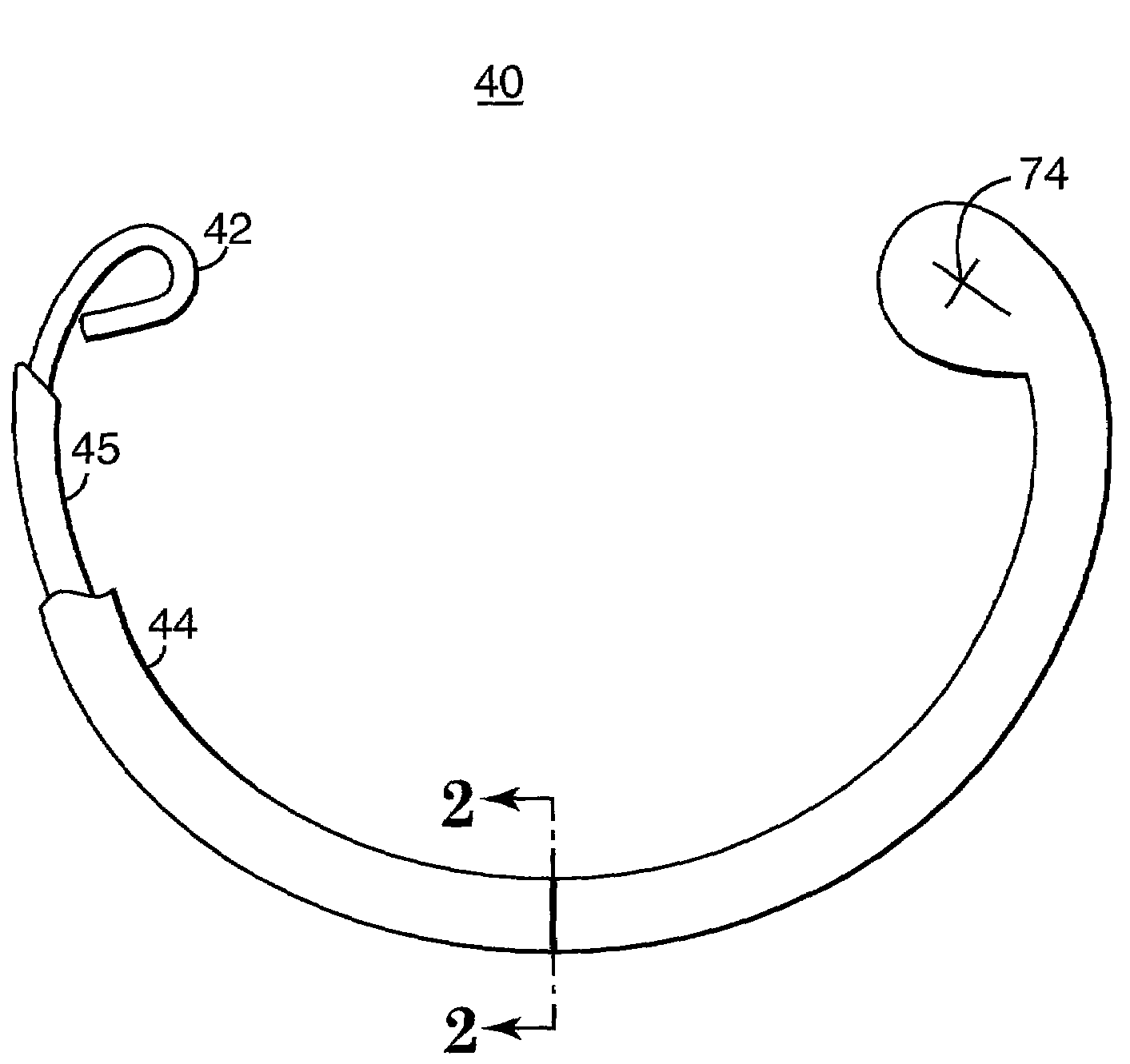
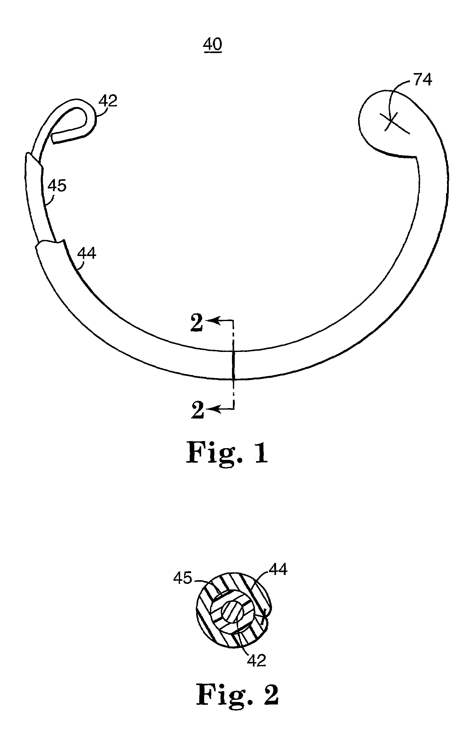
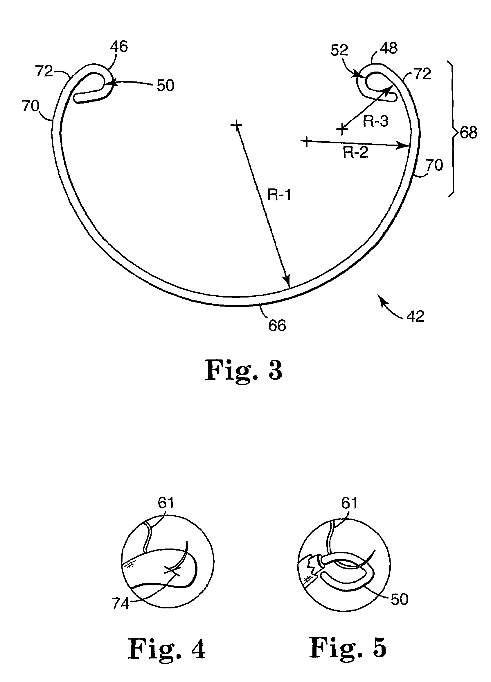
[0050]As illustrated in the drawings, and in particular FIG. 1, a preferred embodiment of the annuloplasty band of the invention is designated in its entirety by the reference numeral 40. The annuloplasty band 40 is particularly adapted to repair one of the atrio-ventricular valves, such as the mitral and tricuspid valves. As a point of reference, the annuloplasty band 40 illustrated in FIG. 1 is configured for mitral valve annulus repair, it being understood that other shapes may be incorporated for other valve annulus anatomies (e.g., tricuspid valve annulus). Thus, the present invention is not limited to mitral valve annuloplasty.

[0051]With additional reference to the cross-sectional view of FIG. 2, the annuloplasty band 40 generally includes a stiffening element 42, such as stiffening wire, and a fabric sheath 44 enclosing the stiffening element 42. The preferred stiffening wire 42 is preferably overmolded with a biocompatible, biostable, implantable, medical grade elastomeric m...


PUM


Abstract

An annuloplasty band comprising a sheath, and a generally arcuate stiffening element disposed within the sheath. The stiffening element extends from a first end to a second end, and preferably includes eyelets at its first and second ends adapted to receive sutures to secure the annuloplasty band to a valve annulus. The annuloplasty band preferably has a low profile (e.g., a thickness less than 3 mm). In embodiments intended for mitral valve repair, the eyelets are particularly adapted to receive sutures to secure the annuloplasty band to the antero-lateral trigone and postero-medial trigone. A holder and sizer device useful with the annuloplasty band are also provided.

Description

CROSS-REFERENCE TO RELATED APPLICATIONS[0001]This application claims the benefit of, and incorporates by reference an entirety of, U.S. application Ser. No. 60 / 276,174, filed on Mar. 15, 2001.FIELD OF THE INVENTION[0002]This invention relates generally to devices and methods for repair of heart valves, such as annuloplasty rings and bands, and more particularly to an annuloplasty band, annuloplasty band holder, annuloplasty sizer and annuloplasty method.BACKGROUND OF THE INVENTION[0003]Annuloplasty prostheses, generally categorized as either annuloplasty rings or annuloplasty bands, are employed in conjunction with valvular reconstructive surgery to assist in the correction of heart valve defects such as stenosis and valvular insufficiency. There are two atrio-ventricular valves in the heart. That on the left side of the heart known as the mitral valve, and that on the right side known as the tricuspid valve. Anatomically speaking, each valve type forms or defines a valve annulus an...

Claims


Application Information

Patent Timeline
Patent Type & Authority Patents(United States)
IPC IPC(8): A61F2/24A61B17/00A61B17/04
CPCA61F2/2445A61F2/2448A61F2/2466A61F2/2496
Inventor RYAN, TIMOTHY R.MORROW, JOSEPH C.
Owner MEDTRONIC INC
Why Eureka
Try Eureka