Mid-line connector and method for pipe-in-pipe electrical heating

a technology of electrical heating and connectors, which is applied in the direction of pipe heating/cooling, connection contact material, mechanical equipment, etc., can solve the problems of difficult removal of plugs, and adversely affecting fluid flow in the pipeline, so as to prevent deterioration of couplers or pockets

Active Publication Date: 2005-03-10
SHELL OIL CO
View PDF16 Cites 400 Cited by
  • Summary
  • Abstract
  • Description
  • Claims
  • Application Information

AI Technical Summary

Benefits of technology

[0016] The mid-line connector may be connected easily to a power generator with an electric cable. The mid-line connector may have an electrically conductive flexible inner pipe connection which enables relative movement between the inner pipe and the outer pipe. The mid-line connector may have a layer of copper coating on the inner pipe where the electric conductor is connected to the inner pipe so as to reduce local hating caused by poor contact resistance. The mid-line connector may also have a moisture control protective layer coated on the exterior of the inner pipe to prevent the inner pipe from oxidation, corrosion and / or build up of oxidation particles. The mid-line connector may be capable of high axial loading. The mid-line connector may also be equipped with dummy plugs to prevent electrical couplers from decay. The mid-line connector may be oriented when placed on the sea floor so that electrical couplers are easily accessible on top of the mid-line connector. The mid-line connector may also have its exterior surfaces deliberately left bare so that potential difference may exist over a large surface area, preventing localized accumulation of stray current. The mid-line connector may also have inner and outer body configurations adaptable to different flowline diameters without modifying shape, strength, or geometry of the connector. The pipe-in-pipe heating system may also have foam in an annulus between the pipes to prevent relative movement between the pipes.
[0023] Still another aspect of the invention is a mid-line connector equipped with dummy plugs in electric couplers or pockets to prevent deterioration of the couplers or pockets during periods of electrical inactivity.

Problems solved by technology

(4.4° C.)) in deep water offshore hydrocarbon recovery operations, hydrocarbon fluids flowing through subsea pipelines become very viscous or deposit paraffin when the temperature of the fluid drops, adversely affecting fluid flow in the pipeline.
Hydrates can plug pipelines and the plugs may be very difficult to remove.
Voltage drop is limited by the dielectric strength and thickness of electrical insulation available.
Because mid-line connector may be electrically unused for long periods of time, a mid-line connector which will not allow its electrical contacts to become corroded is needed.

Method used


Image

  • Mid-line connector and method for pipe-in-pipe electrical heating
  • Mid-line connector and method for pipe-in-pipe electrical heating
  • Mid-line connector and method for pipe-in-pipe electrical heating

Examples


Embodiment Construction

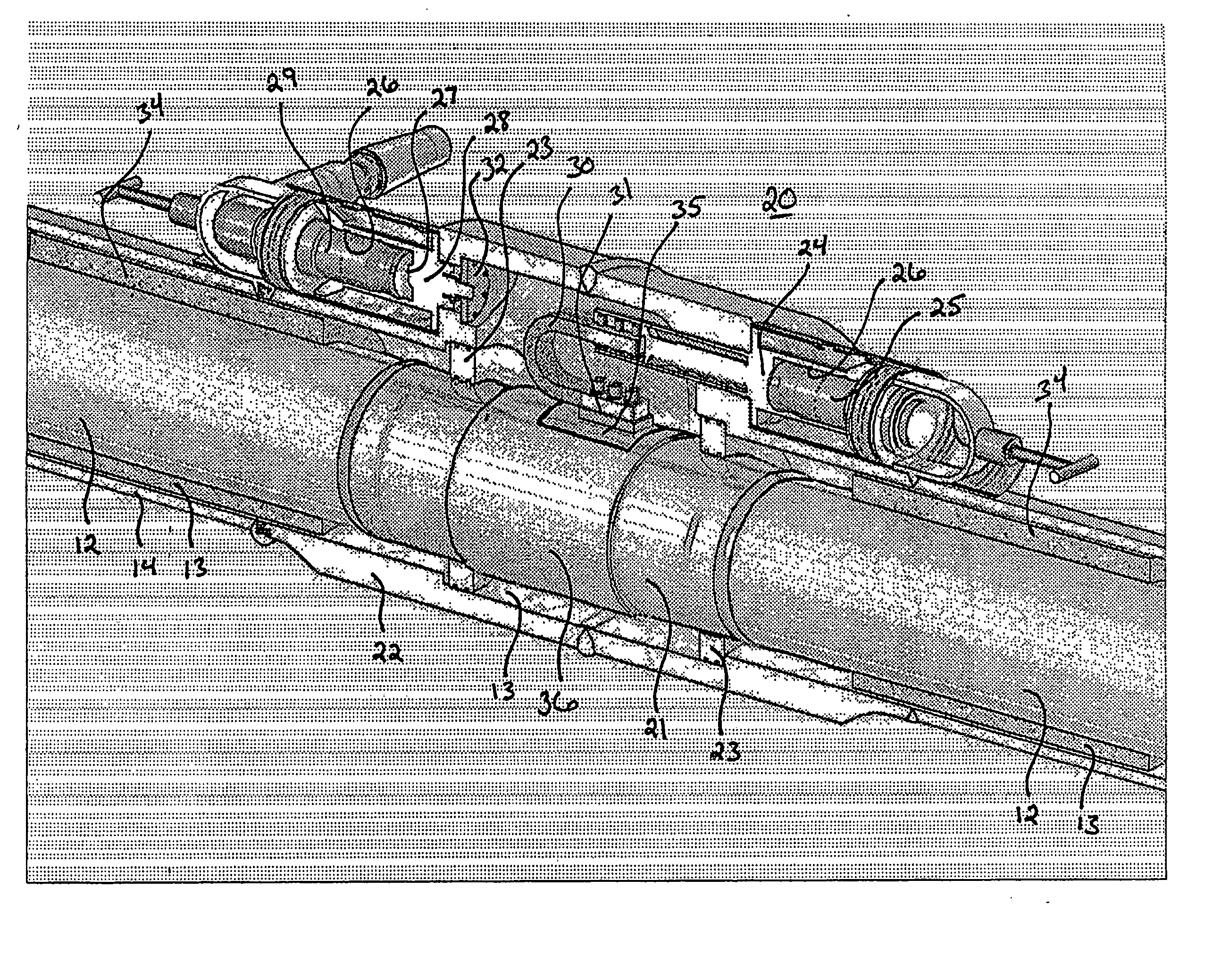
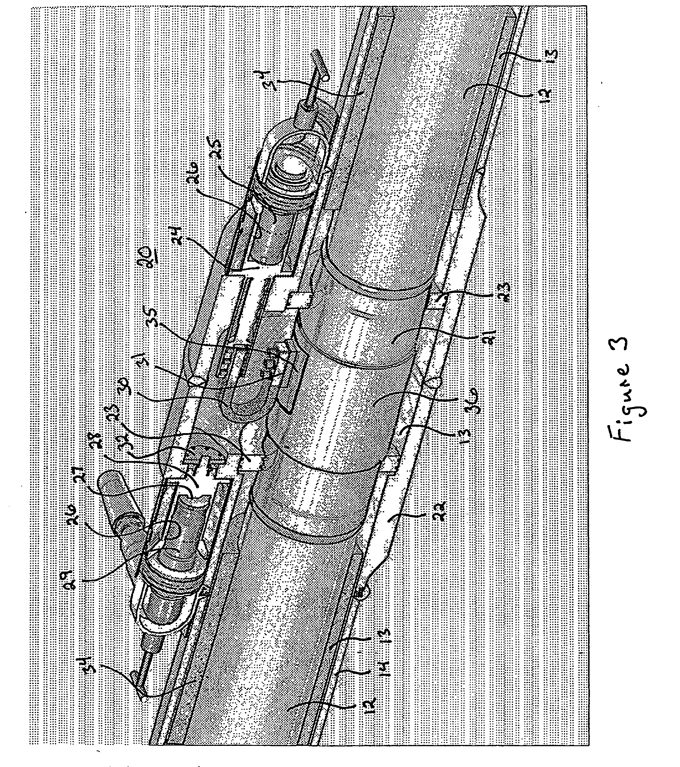
[0034] Referring to FIG. 3, a perspective view of an embodiment of a mid-line connector of the present invention is illustrated. The mid-line connector 20 is inserted into a heating segment 10 of a pipeline 2 between adjacent pipe sections of the pipeline 2. Adjacent sections of the flow line 12 are connected to each other by a blank pipe section 21 which is welded to the ends of the adjacent sections of the flow pipe 12. The adjacent sections of the outer pipe 14 are connected to each other by a connector housing 22 which is welded to the sections of the outer pipe 14. As previously described, an annulus 13 is defined between the flow pipe 12 and the outer pipe 14. This annulus is similarly defined between the blank pipe section 21 and the connector housing 22. Spacer rings 23 may be positioned in the annulus 13 to ensure proper distance is maintained between the blank pipe section 21 and the connector housing 22. The spacer rings 23 may be non-conducting centralizers which maintai...


PUM


Abstract

For heating a pipe-in-pipe pipeline with power provided through an electric cable, mid-line connector is provided including: a connector housing joinable to the outer pipe of the pipeline; a blank pipe positioned within the connector housing and joinable to the inner pipe of the pipeline; at least one pocket mounted in the connector housing, wherein the cable is mateable with the at least one pocket; a blank pipe conductor electrically coupled between the at least one pocket and the blank pipe; and an outer pipe conductor electrically coupled between the at least one pocket and the outer pipe.

Description

[0001] This application claims priority on U.S. Provisional Application 60 / 467,084, filed on May 1, 2003. FIELD OF THE INVENTION [0002] The present invention relates to electrical heating of subsea pipelines. More particularly the invention relates to electrical heating with a pipe-inside-pipe configuration and a connector to the pipes about midway between bulkheads at each end. BACKGROUND OF THE INVENTION [0003] Due to cool water temperatures (about 40° F. (4.4° C.)) in deep water offshore hydrocarbon recovery operations, hydrocarbon fluids flowing through subsea pipelines become very viscous or deposit paraffin when the temperature of the fluid drops, adversely affecting fluid flow in the pipeline. Hydrocarbon gas under pressure combines with water at reduced temperatures to form a solid material, called a “hydrate”. Hydrates can plug pipelines and the plugs may be very difficult to remove. [0004] One solution involves electrical heating of the subsea pipeline to prevent excessive...

Claims


Application Information

Patent Timeline
Patent Type & Authority Applications(United States)
IPC IPC(8): F16L53/37
CPCF16L9/18F16L25/01F16L53/007F16L53/37F16L53/00
Inventor MARCH, DAVID MARTIN
Owner SHELL OIL CO
Why Eureka
Try Eureka