Straight beam buckling electrostatic type micro mechanical optical switch

A micro-mechanical and electrostatic technology, applied in the direction of optics, optical components, optical waveguide coupling, etc., can solve the problems of device stability and reliability, heat can not be effectively dissipated, shorten the service life of devices, etc., to reduce the Effect of driving voltage and deformation time, simple structure, and improved reliability

Inactive Publication Date: 2015-02-18
XIDIAN UNIV
View PDF2 Cites 0 Cited by
  • Summary
  • Abstract
  • Description
  • Claims
  • Application Information

AI Technical Summary

Problems solved by technology

[0005] 1) Using unidirectional loading to drive microbeams requires too high a driving voltage and consumes too much energy
[0006] 2) The structure is relatively complex and difficult to control
[0008] 1) The use of electromagnetic driving methods will bring about electromagnetic interference problems, which will have a certain impact on the stability and reliability of the device;
[0009] 2) The state of the switch needs to be maintained by continuous current. The power consumption of the device is relatively large, and the heat generated by the coil inside the cantilever beam cannot be effectively dissipated, which shortens the service life of the device.

Method used


Image

  • Straight beam buckling electrostatic type micro mechanical optical switch
  • Straight beam buckling electrostatic type micro mechanical optical switch
  • Straight beam buckling electrostatic type micro mechanical optical switch

Examples


Embodiment Construction

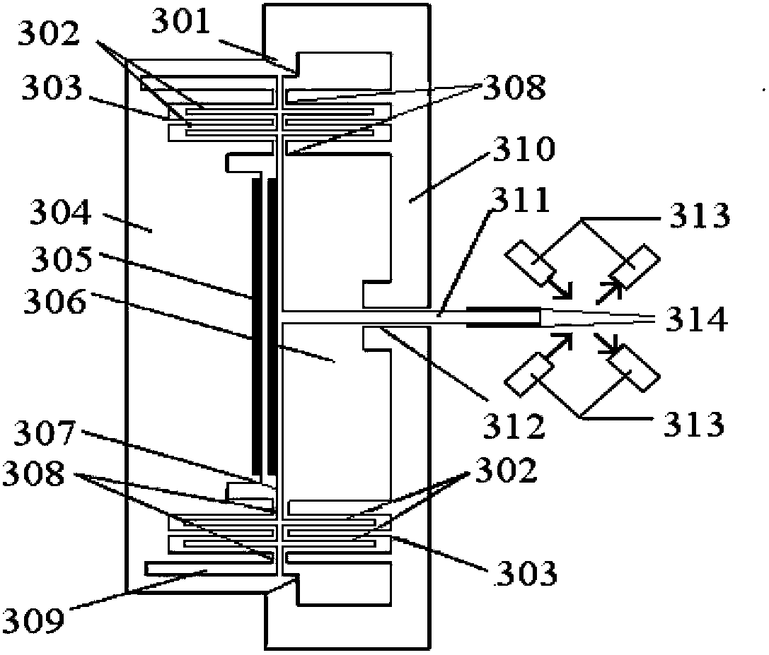
[0036] refer to image 3 , the straight beam buckling electrostatic micromechanical optical switch of the present invention is mainly composed of micro beam 307, fixed base 304, outer frame 310, guide mechanism 308, drive electrode pair 305, 306, adjustment electrode pair 302, 303, guide groove 312, micro The mirror bracket 311, the micro mirror 314 and the optical fiber 313 are composed. Wherein the optical fiber 313 is vertically intersected to form an optical path, the middle position of the microbeam 307 is a rhombus structure, two guide mechanisms 308 are provided, which are respectively located at the upper and lower ends of the fixed base 304, and the micromirror holder 311 is a square cylinder structure.

[0037] The microbeam 307 is integrated with the fixed base 304, and a span support structure 309 is used at the connection position of the two to increase the axial load on the microbeam 307 to reduce the driving voltage and shorten the switch response. time. The mic...


PUM


Abstract

The invention discloses a straight beam buckling electrostatic type micro mechanical optical switch which mainly solves the problem that the existing switch is high in driving voltage, long in switching time, high in energy consumption and the like. The straight beam buckling electrostatic type micro mechanical optical switch comprises a micro beam (307) with a diamond-shaped structure in the middle position, a fixed base (304), an outer framework (310), driving electrode pairs (305 and 306), adjusting electrode pairs (302 and 303), a micro reflecting mirror (314) and optical fibers (313), wherein the micro beam (307) is connected with the fixed base (304) together, and a span supporting structure (309) is adopted at the junction of the micro beam (307) and the fixed base (304); the fixed base (304) is fixed with the outer framework (310) through a wedge-shaped extrusion structure (301), and guide mechanisms (308) are arranged at the two ends of the fixed base (304); the adjusting electrode pairs (302 and 303) adopt comb tooth-shaped structures and are symmetrical to each other up and down; a guide groove (312) is formed in the middle position of the outer framework (310); the optical fibers (131) are perpendicularly placed in a crossed manner; and the micro reflecting mirror (314) is fixed at the front end of a micro mirror bracket (311). The straight beam buckling electrostatic type micro mechanical optical switch has the advantages of low driving voltage, short switching time, low energy consumption and expandable switch array and can be used for key optical devices of optical communication network equipment.

Description

technical field [0001] The invention belongs to the technical field of optoelectronic devices, and in particular relates to an electrostatic micromechanical optical switch, which can be used to realize optical path selection in optical communication, cross interconnection of multiple optical fiber lines, upper and lower optical paths, and bypass of faulty optical fiber lines. technical background [0002] Straight beam buckling electrostatic micromachined optical switch is processed by MEMS technology. Based on the vertical and horizontal bending theory of micro-beams, it breaks through the traditional concept of one-way loading of micro-mechanical optical switches, and uses the spring characteristics of elastic energy release and stiffness changes in micro-beams during buckling deformation to transform elastic force into driving force to realize The purpose of the micromachined optical switch is low driving voltage, short switching time, and low energy consumption. It has ...

Claims


Application Information

Patent Timeline
Patent Type & Authority Patents(China)
IPC IPC(8): G02B6/35G02B26/08
Inventor 田文超山磊
Owner XIDIAN UNIV
Why Eureka
Try Eureka