Method and device for dynamically monitoring microtopography and landforms near seabed

A technology of dynamic monitoring and micro-topography, which is applied in surveying devices, surveying and navigation, open-air water source surveying, etc., can solve the problems of variable slope, difficult to accurately release instruments and devices, and high requirements for instruments, so as to increase inertia, facilitate installation, The effect of quality assurance

Active Publication Date: 2013-12-11
SECOND INST OF OCEANOGRAPHY MNR
View PDF14 Cites 14 Cited by
  • Summary
  • Abstract
  • Description
  • Claims
  • Application Information

AI Technical Summary

Problems solved by technology

[0004] At present, the existing near-bottom dynamic observation technology mainly has the following shortcomings: (1) The bottom shape and bottom quality of the bottom of the seabed are complex and changeable, which is not only reflected in the changeable slope of the bottom topography, but also in the changeable bottom quality of the bottom of the seabed, which may be sand , mud or bedrock, making it difficult to deploy the instrument; (2) The instrument has high requirements for the deployment location, and it is often necessary to find a very flat sea area for instrument release, because whether the instrument is vertical to the seabed directly affects the data quality, but in It is difficult to realize the accurate release of instruments and devices on dynamic ships; (3) There are few types of seabed topography data detected by existing instruments and equipment, and it is difficult to reveal the change law of seabed topography and topography, and it is also difficult to ensure the safety of seabed topography

Method used


Image

  • Method and device for dynamically monitoring microtopography and landforms near seabed
  • Method and device for dynamically monitoring microtopography and landforms near seabed
  • Method and device for dynamically monitoring microtopography and landforms near seabed

Examples


Embodiment 1

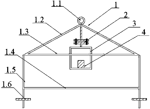
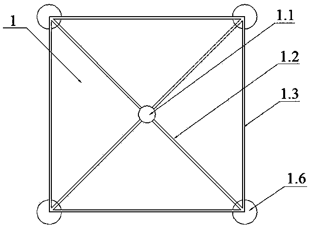
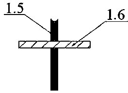
[0043] A dynamic monitoring device for micro-topography and landform near the seabed, referring to the attached figure 1 , 2 , the quadrilateral frame 1 consists of a pull ring 1.1, an inclined quadrilateral frame 1.2, an upper bracket 1.3, a lower bracket 1.4, a pillar 1.5 and an anti-sag plate 1.6 (refer to the attached image 3 , 4 ) to form the outer frame of the device; the oblique quadrilateral frame 1.2 is a quadrangular pyramid structure, the pull ring 1.1 is connected to the top corner of the oblique quadrilateral frame 1.2, and the pull ring 1.1 acts as a delivery and marking device; the oblique quadrilateral frame 1.2 is connected to the upper bracket at the four corners 1.3, the lower bracket 1.4 and the pillar 1.5 play the role of load-bearing and reinforcement devices; the tail end of the pillar 1.5 is connected with the anti-sink plate 1.6, and the circular anti-sink plate 1.6 increases the force-bearing area of ​​the device. The center of the four-sided frame...

Embodiment 2

[0045]A dynamic monitoring device for micro-topography near the seabed, the upper flange 2.3 and the lower flange 2.5 of the connecting part 2 are fixed through the upper screw hole 2.4 and the lower screw hole 2.6, and the instrument compartment 3 can be disassembled and replaced as required; The warehouse 3 fixes the micro-topography dynamic monitoring instrument group 4 through the instrument hole 3.3 at the bottom of the warehouse, and can add or replace instruments according to different research purposes. All the other are with embodiment 1.

Embodiment 3

[0047] A method for dynamic monitoring of micro-topography near the seabed, comprising the following steps:

[0048] Step 1: Device connection and instrument debugging

[0049] 1.1) Check whether the quadrilateral frame 1, connecting part 2, and instrument compartment 3 of the device are welded firmly, whether the steering of the cardan shaft 2.1 is flexible and normal, whether the upper flange 2.3 and the lower flange 2.5 are The connection is firm, and whether the described micro-topography dynamic monitoring instrument group 4 is fixed;

[0050] 1.2) Check whether the pressure sensor 4.1, the altimeter 4.2, the storage unit 4.3, the three-dimensional sonar 4.4, and the submarine camera 4.5 are working normally; connect the altimeter 4.2 and the submarine camera 4.5 to the computer, and check whether the data is received normally;

[0051] Step 2: Device launch

[0052] 2.1) Measure the height from the altimeter 4.2 to the bottom of the device as a basis for judging whet...


PUM


Abstract

The invention discloses a method and a device for dynamically monitoring microtopography and landforms near seabed. The device for dynamically monitoring microtopography and landforms near seabed comprises a four-side frame, a connecting part, an instrument compartment and a dynamic microtopography and landforms monitoring instrument unit. The method for dynamically monitoring microtopography and landforms near seabed includes the steps of device connection, instrument debugging, device arrangement, device operation and recovery, etc. The device can be used for detecting tidal change, sequential variation of water depths at fixed point, three-dimensional seabed landform change and seabed micro-landform change in real time, thereby achieving the purpose of monitoring the change of seabed micro-landforms. The device and the method are suitable for dynamically observing landforms of seabed with various bed forms and bottom substrates, and are safe and stable. The device is convenient to install and disassemble and can be integrated with multiple marine observation instruments. The method and the device can be widely applied to detection of landforms near seabed, marine charting, marine monitoring, ocean engineering and marine scientific research.

Description

technical field [0001] The invention relates to a dynamic observation method and device near the seabed, in particular to a method and device for dynamic monitoring of micro-topography near the seabed. Background technique [0002] The monitoring support of seabed topography and landform changes is the basis of ocean forecasting, engineering design, resource development, ocean management, sea area demarcation, national defense security and seabed scientific research. Due to natural factors, such as sediment movement, hydrodynamics, weather processes and emergencies, as well as the complex influence of human activities, the topography of the seabed in these areas often undergoes drastic changes, and even fatal consequences. Serious submarine disasters, environmental The deterioration and imbalance of the ecosystem directly affect the development of the marine economy, the safety of waterways, and the safety of marine engineering. [0003] Repeated measurement using tradition...

Claims


Application Information

Patent Timeline
Patent Type & Authority Applications(China)
IPC IPC(8): G01C13/00
Inventor 吴自银周洁琼李守军尚继宏赵荻能周勐佳
Owner SECOND INST OF OCEANOGRAPHY MNR
Why Eureka
Try Eureka