Blind rivet

a technology of blind rivets and rivets, which is applied in the direction of fastening means, screws, dowels, etc., can solve the problems of requiring considerable remedial work to rectify failures, and achieve the effects of improving shear resistance, large bearing area, and convenient availability

Inactive Publication Date: 2007-01-11
NEWFREY
View PDF13 Cites 14 Cited by
  • Summary
  • Abstract
  • Description
  • Claims
  • Application Information

AI Technical Summary

Benefits of technology

[0031] The closest prior art is shown in EP-A-0595041—Bollhoff & Co. EP-A-0595041 illustrates a variety of threaded inserts. EP-A-0945631—Emhart Inc. shows a male threaded blind insert. Neither EP-A-0595041 nor EP-A-0945631 show, however, the threaded insert being used in a blind rivet that is capable of supporting a shear load, since there is clearance between the pulling mandrel diameter and the bore of the insert. This clearance allows the rivet body to tilt being unsupported internally.
[0032] The blind rivet of the present invention offers several advantages. The blind rivet is of large diameter thus providing improved shear resistance and a large bearing area against applied loads. The blind rivet is constructed with a body similar to a threaded insert product that is readily available and an easily produced pulling mandrel. Thus the rivet can be produced on readily available manufacturing machines. This invention, thus, avoids the use of much larger and slower cold forging machines which would have been necessary if a large diameter rivet of a conventional design had been adopted. The blind rivet body is provided with a grooved body that will give it a wider grip capability than the standard type of threaded insert. The pulling mandrel is provided with a shouldered portion that, being in direct contact with the collapsing bore of the rivet body, supports the body against applied shear forces unlike conventional mandrels that are uniform in diameter. The blind rivet can be fully sealed from ingress of moisture or vapours through the centre of the product which is a distinct advantage over usual male threaded inserts.

Problems solved by technology

There are two problems that exist which require resolution.
Should the mandrel fail to detach, considerable remedial work is required to rectify the failure.
Just as with U.S. Pat. No. 4,826,372, there is a problem should the mandrel fail to snap off at the end of the blind riveting operation.

Method used


Image

  • Blind rivet
  • Blind rivet

Examples


Embodiment Construction

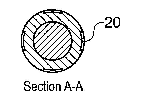
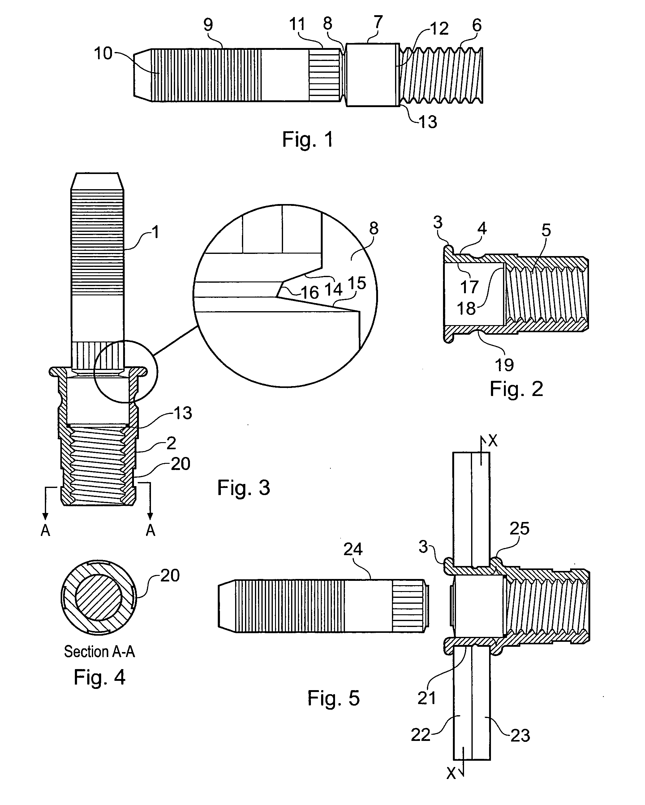
[0039] Referring together to the attached Figures, the rivet shown comprises a mandrel 1 that is assembled to a threaded insert or rivet body 2 by screwing the threaded portion 6 of the mandrel into the rivet body 2 where it is staked or swaged such that it becomes an integral part of the rivet body.

[0040] Referring to FIG. 2, the rivet body is characterised by a flange 3, a thin walled collapsing portion 4 and an internally threaded portion 5. The internal bore of the rivet body 17, which determines the collapsing portion, meets the threaded portion in a shoulder 18. Rivet bodies of this type have only a small grip range typically about 1-1.5 mm so in order to improve this range a radial groove 19 is formed in the rivet body midway between the underside of the flange and the internal shoulder 18.

[0041] Referring to FIG. 1 the mandrel 1 is shown with a male threaded portion 6, an enlarged diameter portion 7, a breaker groove 8 and a tail or pulling portion 9 that is smaller in dia...


PUM


Abstract

A blind rivet assembly includes a mandrel having a male threaded portion at its distal end to be screwed into an internal female threaded portion of a rivet body. The mandrel has a section of enlarged diameter adjacent the male threaded portion joined by a breaker groove to a pulling portion. The section of enlarged diameter is accommodated within an internal bore of the collapsing portion of the rivet body, the collapsing portion having a radial groove on the outer surface thereof for improving the radial expansion of the rivet when installed. A shoulder in the internal bore supports a sealing ring. When assembled correctly, the pulling portion breaks off at the breaker groove.

Description

CROSS-REFERENCE TO RELATED APPLICATION [0001] This application claims priority under 35 U.S.C. §119(a) of commonly assigned British Patent Application No. 0511793.2, filed Jun. 10, 2005. The disclosure of the above application is incorporated herein by reference. BACKGROUND [0002] The present invention relates to blind rivets, and more particularly, but not exclusively, to a blind rivet with high shear resistance. [0003] A blind rivet assembly normally comprises a rivet body and a mandrel assembly. The rivet body comprises a flange portion and a cylindrical body that extends from the flange portion and an axial hollow bore that passes through the rivet body. A mandrel typically comprises a head portion and a long stem that passes through the rivet body, such that the mandrel head portion abuts a blind-side end of the rivet body. [0004] In use, the rivet assembly is inserted into a prepared hole in a workpiece or application, so that the flange portion of the rivet body abuts an oper...

Claims


Application Information

Patent Timeline
Patent Type & Authority Applications(United States)
IPC IPC(8): F16B13/04F16B19/10F16B37/06
CPCF16B19/1054F16B37/065F16B19/1072F16B19/1045
Inventor HULL, DARREN
Owner NEWFREY
Why Eureka
Try Eureka