Tangential cutting insert and milling cutter

a technology of cutting inserts and milling cutters, which is applied in the direction of metal-working equipment, metal-working apparatus, milling equipment, etc., can solve the problems of affecting the cutting efficiency of the insert, so as to achieve smooth varying profiles

Active Publication Date: 2006-09-12
THE INGERSOLL CUTTING TOOL CO
View PDF36 Cites 38 Cited by
  • Summary
  • Abstract
  • Description
  • Claims
  • Application Information

AI Technical Summary

Benefits of technology

[0008]It is an object of the present invention to provide a double-sided indexable tangential cutting insert having four main cutting edges, for a given direction of rotation of the milling cutter, each main cutting edge having a positive axial rake angle when mounted as an operative cutting edge in a milling cutter. Preferably, such a double-sided indexable tangential cutting insert is capable of milling a square shoulder in a workpiece. It is a further object of the present invention to provide a milling cutter in which a cutting insert in according to the present invention can be retained.
[0019]Preferably, in each cross section of the cutting insert taken in a plane parallel to the minor plane P1 of the cutting insert, the end surface has a smoothly varying profile.

Problems solved by technology

However, negative axial rake angles are disadvantageous, e.g., they have been found to be deficient in cutting efficiency for applications involving difficult to machine materials.
It will be appreciated that the magnitude of the insert axial rake angle is limited for practical reasons.
Any increase in the insert axial rake angle will result in an increase in the “vertical” extent of the increasing incident angle surface (see FIG. 3 of U.S. Pat. No. 5,333,972) that will have an adverse effect on chip development and evacuation.
Moreover, the axial rake and relief angles are interdependent and any change in the axial relief angle results in a corresponding change in the relief angle, which is not always desirable.
Despite the improvement provided by this cutting insert, the abutment member still presents a chip deflector to chips which in certain circumstances may have an adverse effect on chip development and evacuation, depending on cutting conditions.

Method used


Image

  • Tangential cutting insert and milling cutter
  • Tangential cutting insert and milling cutter
  • Tangential cutting insert and milling cutter

Examples


Embodiment Construction

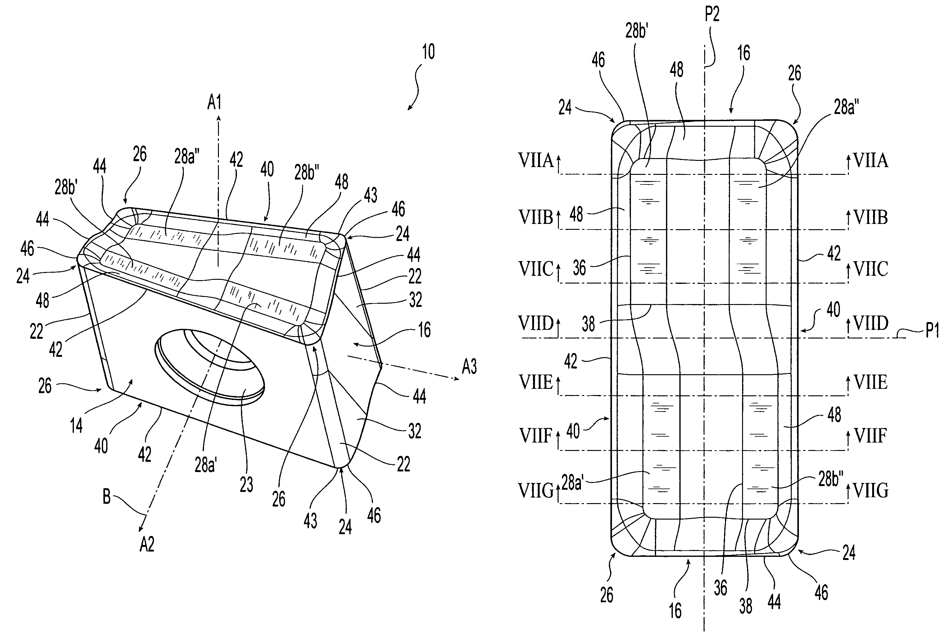
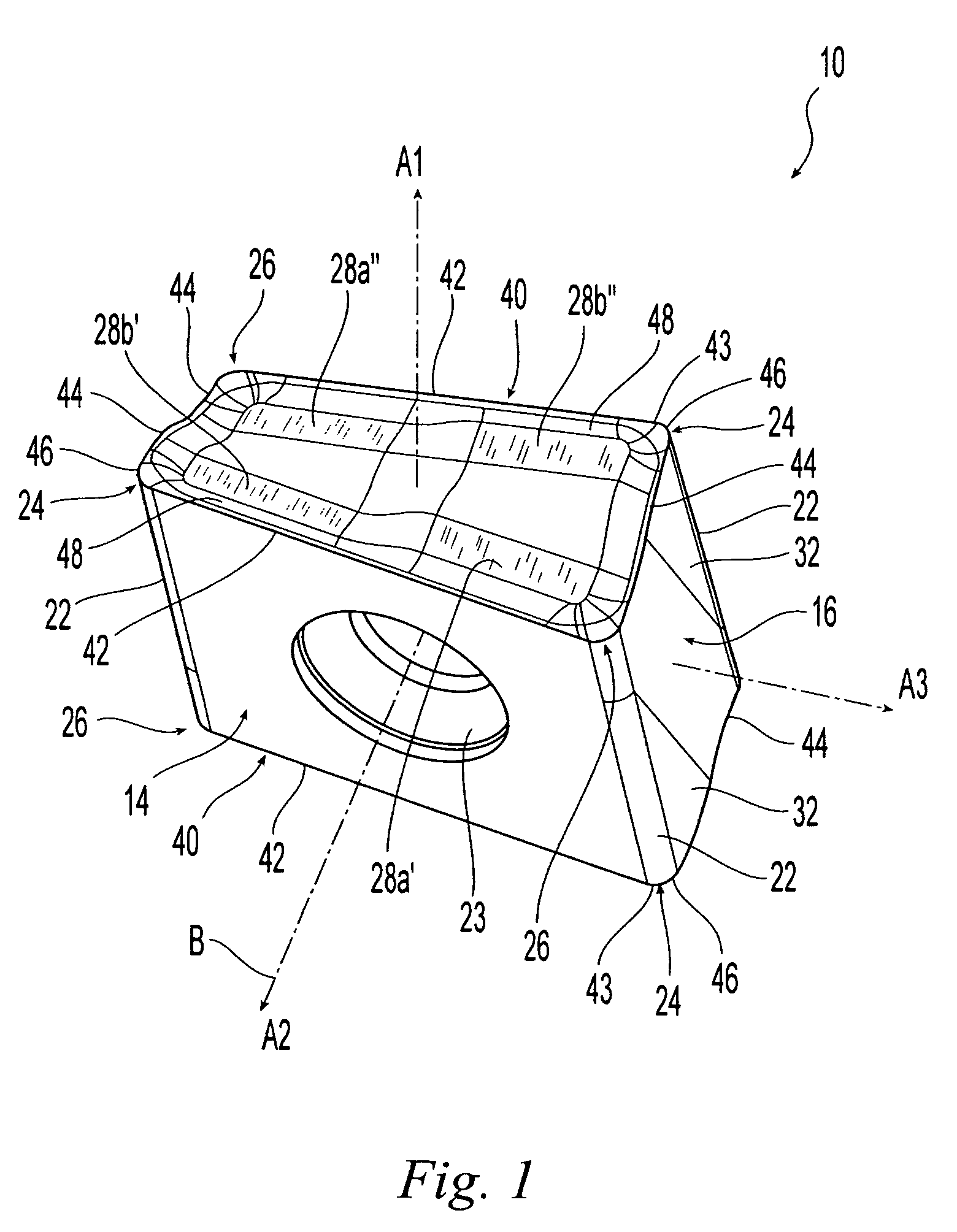
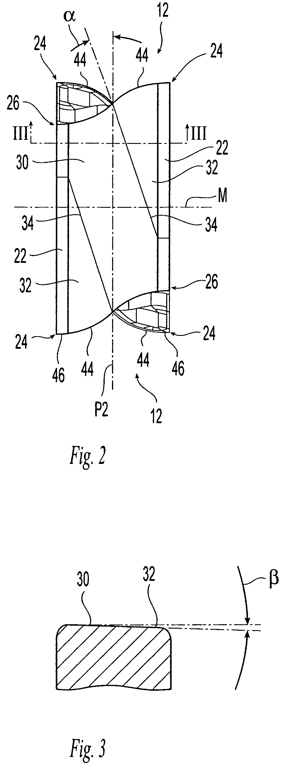
[0070]Attention is first drawn to FIGS. 1 to 6, showing a right-handed cutting insert 10 in accordance with the present invention there. It should be noted that the figures are not drawn to scale. For example, FIG. 4, has been drawn on a larger scale than the other figures, for reasons of clarity. The cutting insert 10 is tangential and indexable, and is typically manufactured by form-pressing and sintering carbide powders. The cutting insert 10 is generally rectangular in an end view and has two identical opposing end surfaces 12. Each end surface 12 has 180° rotational symmetry about a first axis A1 passing through the two end surfaces 12.

[0071]A peripheral side surface 14 extends between the two opposing end surfaces 12 and comprises two opposed identical minor side surfaces 16, two opposed identical major side surfaces 18, and four corner side surfaces 22. Each pair of adjacent minor and major side surfaces 16, 18 are connected at a common corner side surface 22. The two identic...


PUM

PropertyMeasurementUnit
angleaaaaaaaaaa
mirror symmetryaaaaaaaaaa
obtuse angleaaaaaaaaaa

Abstract

A tangential milling cutting insert has two identical opposing end surfaces with two identical opposing major side surfaces of a generally parallelogrammatic shape and two identical opposing minor side surfaces extending between them. An ambidextrous tangential cutting insert has two non-identical end surfaces and two opposing major side surfaces of a generally trapezoidal nature. In either cutting insert, each end surface has a peripheral cutting edge and four corners of which two diagonally opposed corners are lowered and the other two are raised. Each end surface comprises four separate planar regions arranged in pairs, the planar regions do not protrude relative to the surrounding end surface and the two planar regions of a given pair of planar regions slope in opposite directions with respect to a median plane of the cutting insert.

Description

FIELD OF THE INVENTION[0001]The present invention relates to a tangential indexable cutting insert and a milling cutter for use in metal cutting processes in general and for milling a square shoulder in a workpiece in particular.BACKGROUND OF THE INVENTION[0002]Tangential cutting inserts, also known as on-edge, or lay down, cutting inserts, are oriented in an insert holder in such a manner that during a cutting operation on a workpiece the cutting forces are directed along a major (thicker) dimension of the cutting insert. An advantage of such an arrangement being that the cutting insert can withstand greater cutting forces than when oriented in such a manner that the cutting forces are directed along a minor (thinner) dimension of the cutting insert.[0003]There is disclosed in EP 0 769 341 a face milling cutter employing a double-sided indexable tangential cutting insert having a prismoidal shape with two opposed generally rectangular rake surfaces connected by side surfaces. The c...

Claims


Application Information

Patent Timeline
Patent Type & Authority Patents(United States)
IPC IPC(8): B23C5/20
CPCB23C5/06B23C5/2221B23C2200/0472B23C2200/085B23C2200/123Y10T407/1924B23C2200/367B23C2210/168Y10T407/192Y10T407/1936Y10T407/23B23C2200/286B23C5/2213B23C5/20B23C5/00
Inventor JOHNSON, WILLIAM BENNETTVOGELER, NEIL A.
Owner THE INGERSOLL CUTTING TOOL CO
Why Eureka
Try Eureka