Tube fitting with separable tube gripping ring

Active Publication Date: 2006-09-19
SWAGELOK CO
View PDF233 Cites 56 Cited by
  • Summary
  • Abstract
  • Description
  • Claims
  • Application Information

AI Technical Summary

Benefits of technology

[0025]In accordance with one aspect of the invention, a new tube fitting concept requires user assembly of only two components, namely a fitting body and a fitting nut. The nut and body are adapted to be threadably coupled together by relative rotation therebetween. The nut includes an initially integral tube gripping element or ferrule that cooperates with a camming surface on the body when the fitting is made-up. The tube gripping element may be machined with the nut or separately attached thereto by any convenient process such as brazing, welding or soldering, for example. In the described embodiment the tube gripping element is a ring like structure that, after it separates from the component to which it is attached, operates as a single ferrule. The detached ferrule is radially compressed and plastically deformed against the tube outer wall to form a seal and a tight tube grip bite. The detached ferrule also forms a primary seal against the camming surface. In one embodiment, the ferrule includes an outer tapered surface at its front end forming a generally narrow line contact-type seal against the camming surface. The ferrule in one embodiment is designed to have a hinging action and to plastic deform during pull-up to embed the nose portion into the tubing wall for excellent tube grip, and an axially adjacent swage or coll

Problems solved by technology

Secondly, the tube fitting must maintain a primary seal against leakage.
Tube fittings that are intended for use with stainless steel and other metal tubing, for example, are particularly challenging to design in order to achieve the desired tube grip and seal functions.
Heavy wall tubing is difficult to grip because it is not only hard but it is also not particularly ductile.
Low ductility makes it more difficult to deform the tubing plastically so as to achieve a desired tube grip.
These designs are not suitable for high pressure stainless steel tube fittings.
However, it is becoming increasingly recognized that these two functions are at odds with each other when designing a tube fitting that can meet a desired tube grip and seal performance criteria.
This is because the design criteria needed to assure that the tube fitting achieves an adequate tube grip usually works against the ability of the single ferrule to also provide an effective seal.
Consequently, although prior art single ferrule fittings can achieve adequate tube grip in some cases, this tube grip performance comes at the expense of having a less effective seal.
Single ferrule tube fittings thus are usually more

Method used


Image

  • Tube fitting with separable tube gripping ring
  • Tube fitting with separable tube gripping ring
  • Tube fitting with separable tube gripping ring

Examples


Embodiment Construction

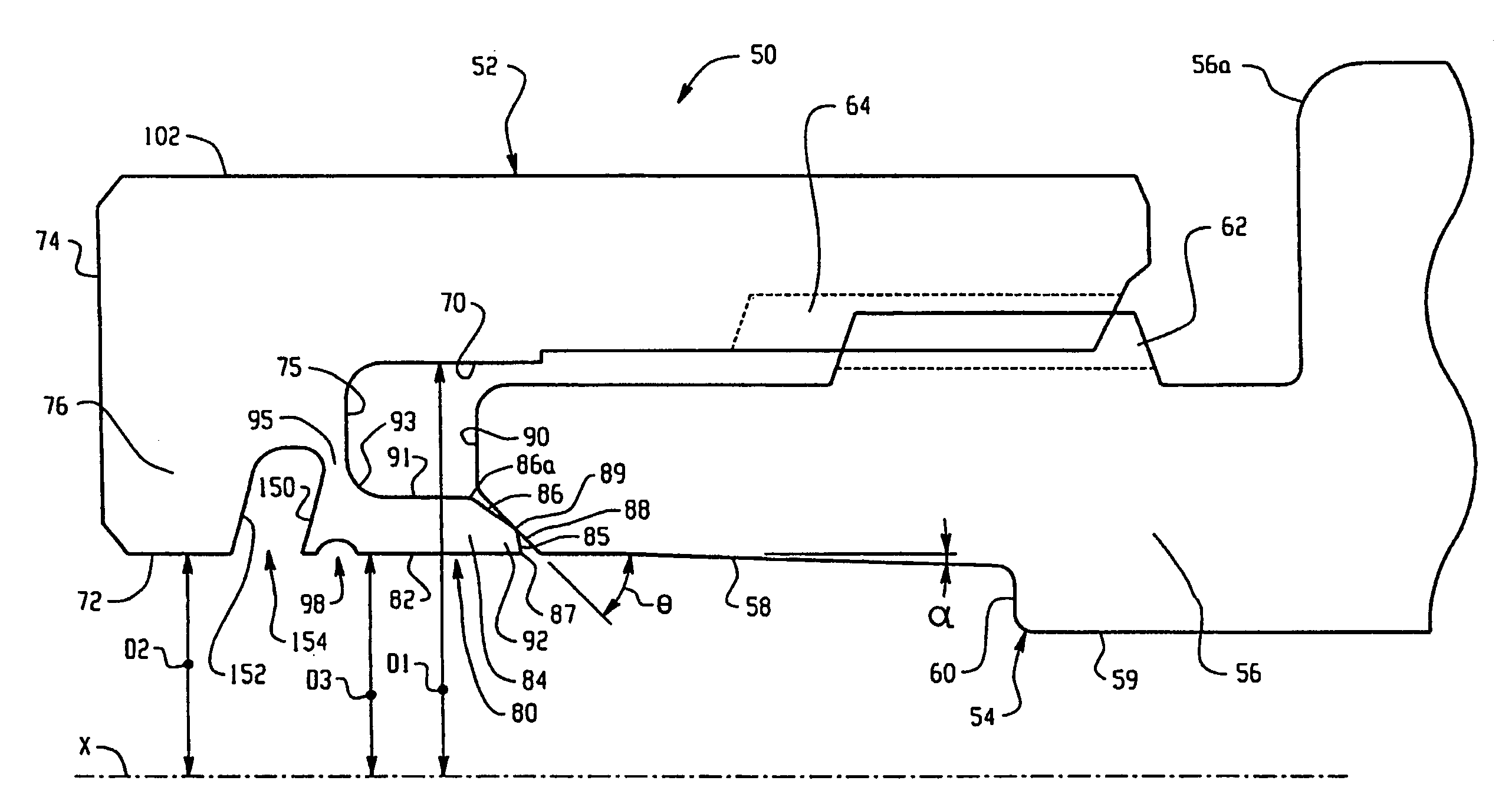
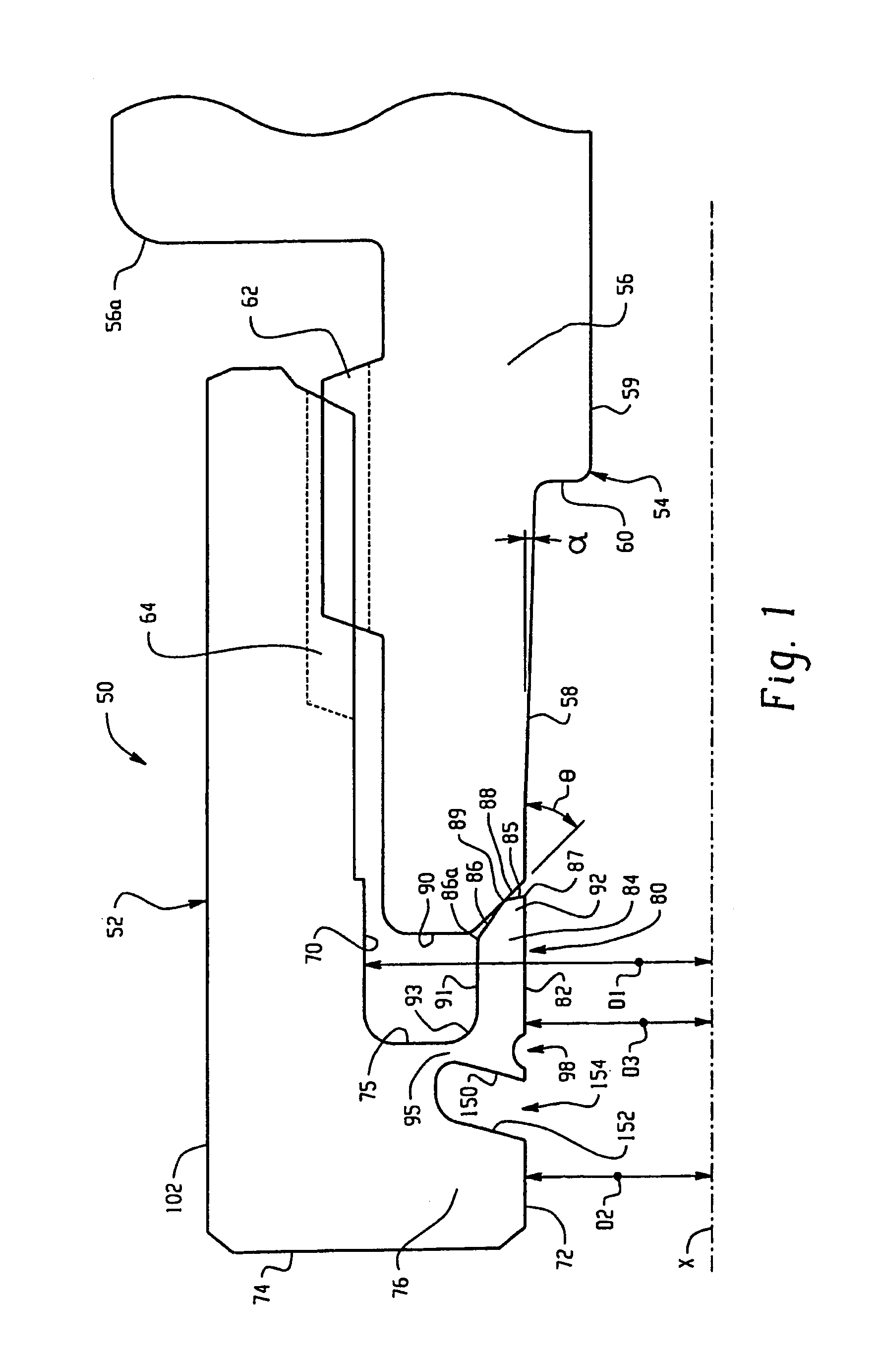
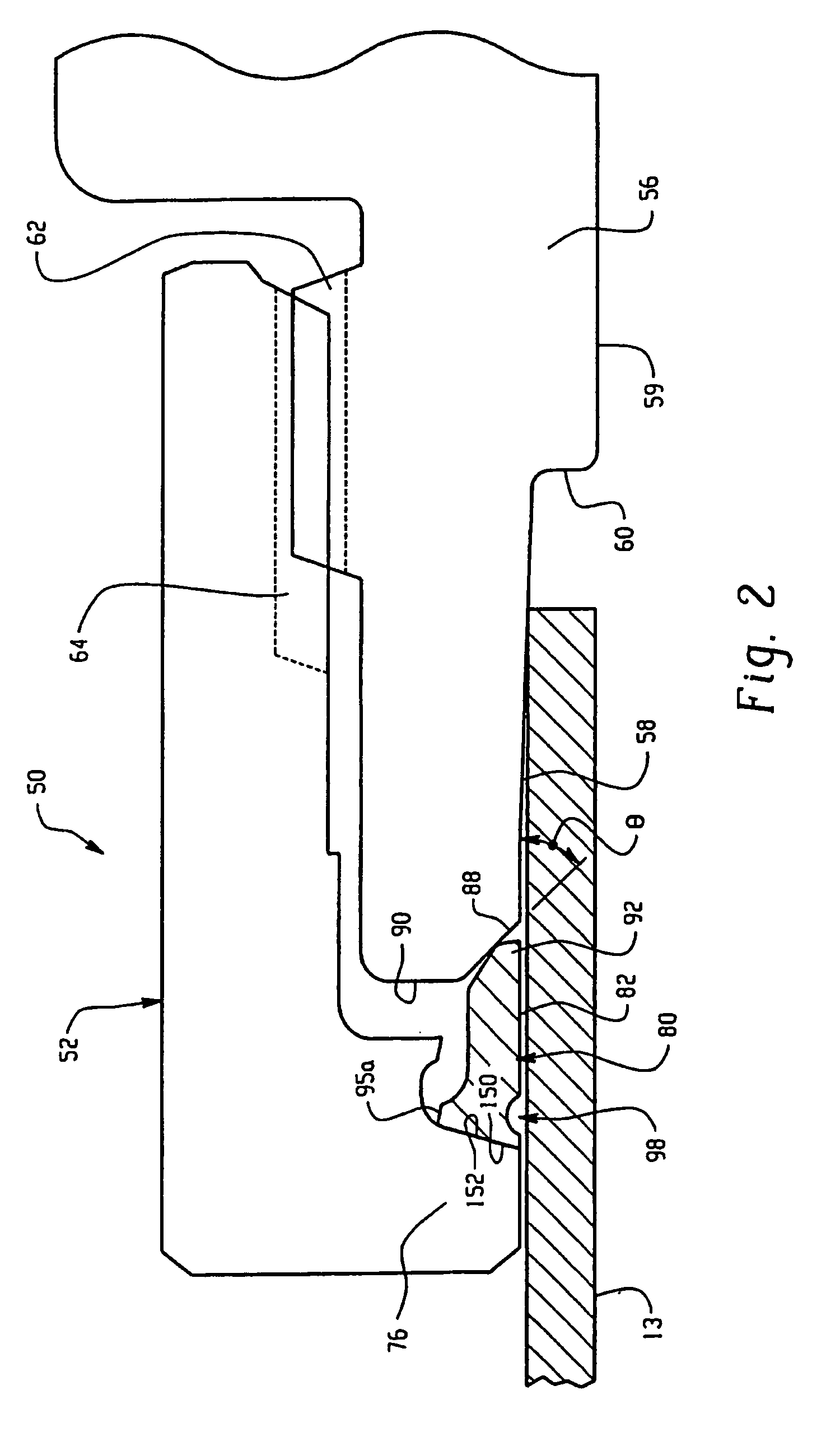
[0033]In accordance then with one aspect of the invention, a tube fitting is provided having a tube gripping device that initially is integral with one of the coupling elements and upon pull-up separates therefrom to function as a single ferrule fitting. In the preferred embodiment, the tube gripping device or ferrule is integrally formed with a female threaded nut and is attached thereto by a frangible thin web portion that breaks as the ferrule cams initially against a camming surface of the male threaded component. As a single ferrule after separation, the ferrule acts against the steep camming angle surface of a male threaded body. The steep camming surface angle is particularly advantageous when the hardness of the tube gripping device has a ratio of at least about 3.3 times greater and preferably at least 4 times greater to the hardness of the tubing material.

[0034]Although a number of aspects of the invention are described herein as being incorporated into the exemplary embod...


PUM

PropertyMeasurementUnit
Angleaaaaaaaaaa
Angleaaaaaaaaaa
Angleaaaaaaaaaa

Abstract

A tube fitting for a tube end has a female threaded member that cooperates with a male threaded member. The female member includes a tube gripping device in the form of a gripping ring or ferrule that is attached to the female member by a fungible web. Upon a partial pull-up the female engages a camming surface on the male threaded member and breaks off or separates from the female threaded member to become a separate piece so that the fitting then functions as a single ferrule tube fitting. Additional features include a steep camming angle on the camming surface to cause the ferrule to grip the tube end with a bite-type action and to form a primary seal between the camming surface and a front end of the separated ferrule. The ferrule front end, and optionally the entire female threaded member including the initially integral tube gripping device, are hardened to be at least about 3.3 times harder than the material of the tube end.

Description

RELATED APPLICATIONS[0001]This application is a national application from International patent application no. PCT / US02 / 03431 filed on Feb. 6, 2002 for TUBE FITTING WITH SEPARABLE TUBE GRIPPTNG RING, both of which claim the benefit of U.S. Provisional patent application Ser. No. 60 / 266,735 filed on Feb. 6, 2001 for TUBE FITTING WITH INTEGRAL NUT AND FERRULE, and Ser. No. 60 / 329,943 filed in Oct. 17, 2001 for TUBE FITTING, the entire disclosures all of which are fully incorporated by reference.TECHNICAL FIELD OF THE INVENTION[0002]The subject invention is generally directed to the art of tube fittings. More particularly, the invention is directed to a flareless tube fitting that uses a tube gripping element that is initially joined to one of the coupling elements and separates therefrom during assembly onto a tube end.BACKGROUND OF THE INVENTION[0003]Tube fittings are used to join or connect a tube end to another member, whether that other member be another tube end such as through T...

Claims


Application Information

Patent Timeline
IPC IPC(8): F16L35/00F16L21/08B32B15/04C23C8/28C23C28/00F16L19/065
CPCF16L19/14C23C28/00C23C8/80C23C8/34F16L19/06
Inventor BENNETT, MARK A.WILLIAMS, PETER C.
Owner SWAGELOK CO
Why Eureka
Try Eureka