Fitting with separable gripping device for pipe and tube

a technology of pipe and tube fittings, applied in the direction of hose connections, couplings, mechanical devices, etc., can solve the problems of difficult difficult to grip heavy wall tubing, and difficult to design in order to achieve the desired tube grip and seal function. , to achieve the effect of excellent tube grip, preventing excessive tightening of components, and excellent tube grip

Inactive Publication Date: 2006-06-27
SWAGELOK CO
View PDF237 Cites 65 Cited by
  • Summary
  • Abstract
  • Description
  • Claims
  • Application Information

AI Technical Summary

Benefits of technology

[0024]In accordance with one aspect of the invention, a new tube fitting concept requires user assembly of only two components, namely a fitting body and a fitting nut. The nut and body are adapted to be threadably coupled together by relative rotation therebetween. The nut includes an initially integral tube gripping element or ferrule that cooperates with a camming surface on the body when the fitting is made-up. The tube gripping element may be machined with the nut or separately attached thereto by any convenient process such as brazing, welding or soldering, for example. In the described embodiment the tube gripping element is a ring like structure that, after it separates from the component to which it is attached, operates as a single ferrule. The detached ferrule is radially compressed and plastically deformed against the tube outer wall to form a seal and a tight tube grip bite. The detached ferrule also forms a primary seal against the camming surface. In one embodiment, the ferrule includes an outer tapered surface at its front end forming a generally narrow line contact-type seal against the camming surface. The ferrule in one embodiment is designed to have a hinging action and to plastic deform during pull-up to embed the nose portion into the tubing wall for excellent tube grip, and an axially adjacent swage or collet zone that isolates the embedded nose portion from vibration effects. The hinging action also helps to keep the ferrule outer tapered surface in a generally line contact with the camming surface. The fitting components, and particularly the separable ferrule, are preferably but not necessarily case hardened. The new fitting is especially useful as a stainless steel and other metal tube fittings, although the invention is not limited to any particular class of metals. In accordance with another aspect of the invention, the fitting may include a self-gauging feature to indicate sufficient pull-up and to prevent excessive tightening of the components.
[0025]In accordance with additional aspects of the invention, the camming surface profile is substantially modified from prior art single ferrule tube fitting designs by incorporating a steep camming angle in the range of about thirty-five degrees to about sixty degrees. The steeper camming angle produces a better tube grip than prior art single ferrule tube fittings, particularly when the ferrule is hardened to a hardness ratio that is at least about 3.3 times on the Vickers scale the hardness of the tubing material. The ferrule may also be designed with a geometry that facilitates a radially inward hinging action during pull-up. This hinging action improves the tube grip and seal as compared to prior single ferrule tube fittings.
[0026]In accordance with a further optional aspect of the invention, the tube gripping device or separable ferrule has a driven face that forms a difference angle with a drive face of the nut upon separation. Still a further option is that the separable ferrule may have a substantially continuous cylindrical interior wall. In accordance with a still further optional aspect of the invention, upon separation a portion of the ferrule driven face is plastically deformed so as to form a contour, such as a convex portion, that facilitates hinging action of the ferrule and may also be used to reduce pull-up torque.

Problems solved by technology

Secondly, the tube fitting must maintain a primary seal against leakage.
Tube fittings that are intended for use with stainless steel and other metal tubing, for example, are particularly challenging to design in order to achieve the desired tube grip and seal functions.
Heavy wall tubing is difficult to grip because it is not only hard but it is also not particularly ductile.
Low ductility makes it more difficult to deform the tubing plastically so as to achieve a desired tube grip.
These designs are not suitable for high pressure stainless steel tube fittings.
However, it is becoming increasingly recognized that these two functions are at odds with each other when designing a tube fitting that can meet a desired tube grip and seal performance criteria.
This is because the design criteria needed to assure that the tube fitting achieves an adequate tube grip usually works against the ability of the single ferrule to also provide an effective seal.
Consequently, although prior art single ferrule fittings can achieve adequate tube grip in some cases, this tube grip performance comes at the expense of having a less effective seal.
Single ferrule tube fittings thus are usually more suited to lower pressure liquid applications such as hydraulics, however, even in such lower pressure applications single ferrule seal performance remains less than desired.
Consequently, an outwardly bowed single ferrule fitting could be more susceptible to ferrule collapse, loss of seal and possibly tube blow out at higher pressures.
The result in such cases however is a low grip or low pressure only fitting that are not well suited to stainless steel fittings.
The shallow camming angle and elongated camming surface and axial movement needed to achieve an adequate tube grip with a single ferrule fitting, however, compromises the ability of the single ferrule to achieve the seal function, especially in extreme environments and for sealing gas.
This enlarged seal area causes an unwanted distribution of the sealing force between the single ferrule and the camming surface, and also creates a larger area for surface imperfections to allow leaks to occur.
The fitting does not appear to be applicable to stainless steel tubing as the tube is covered with a resin cover.
Thus the prior art designs suffer from the same limitations as the prior art single ferrule tube fitting designs.

Method used


Image

  • Fitting with separable gripping device for pipe and tube
  • Fitting with separable gripping device for pipe and tube
  • Fitting with separable gripping device for pipe and tube

Examples


Embodiment Construction

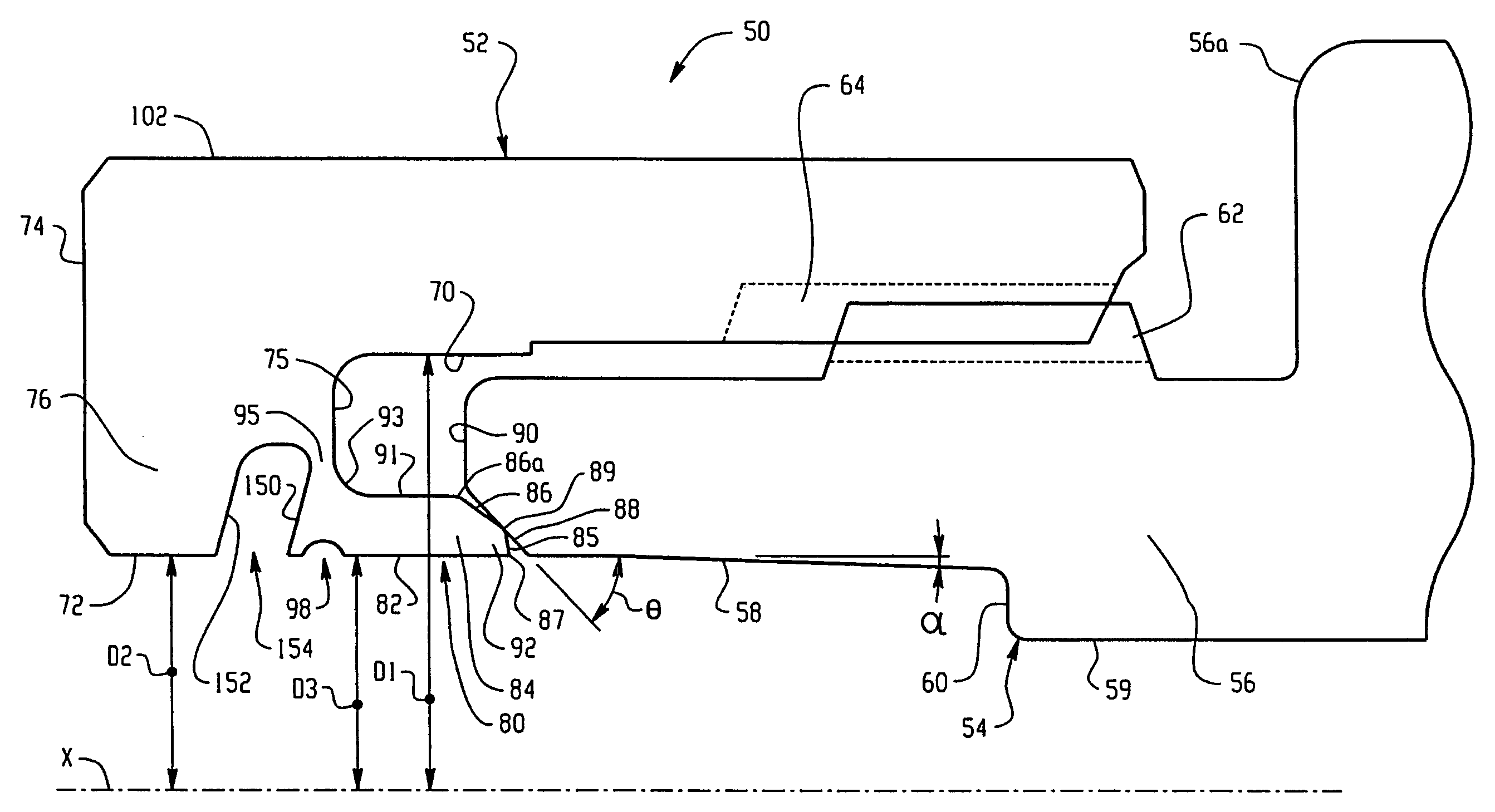
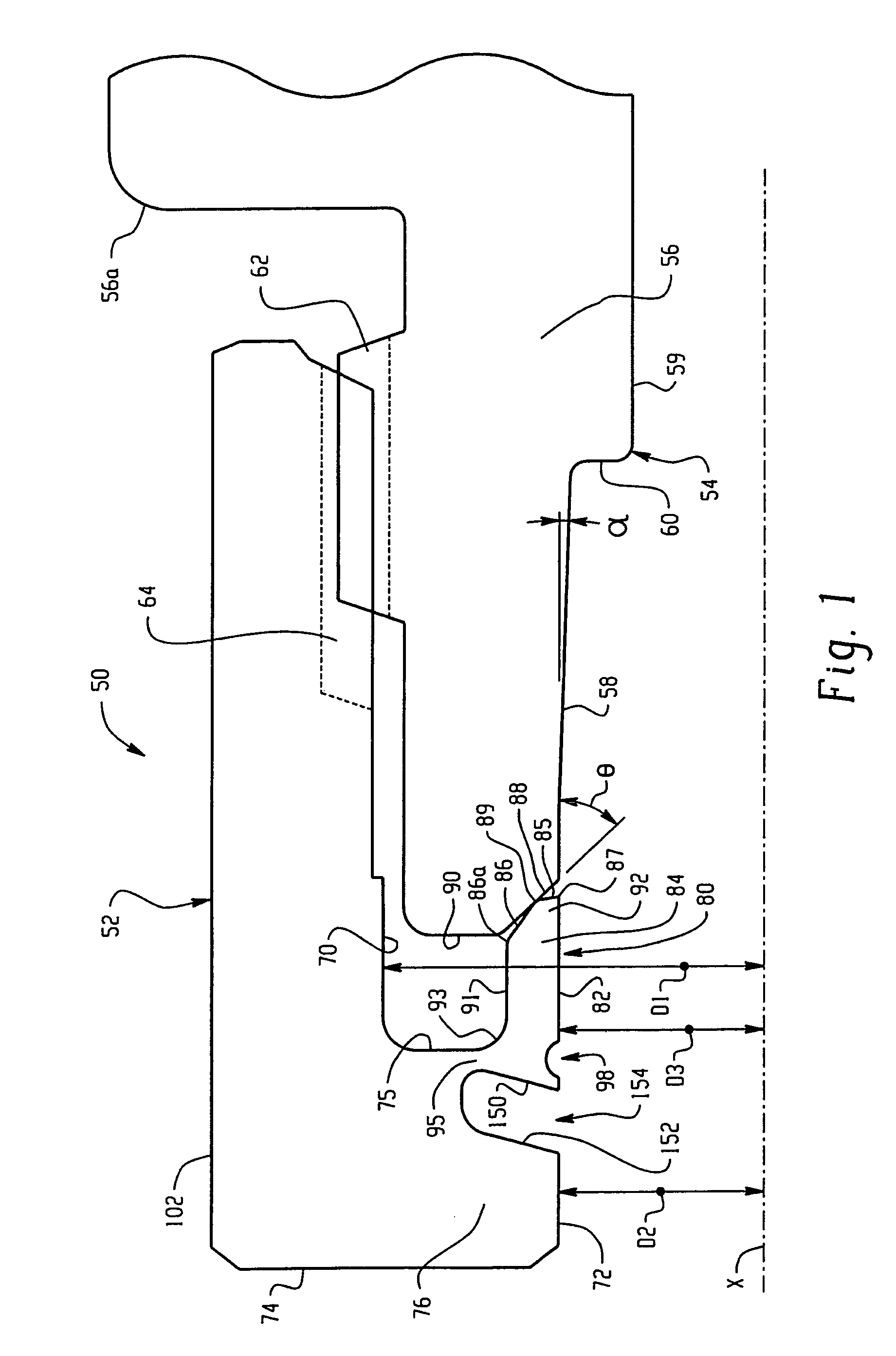
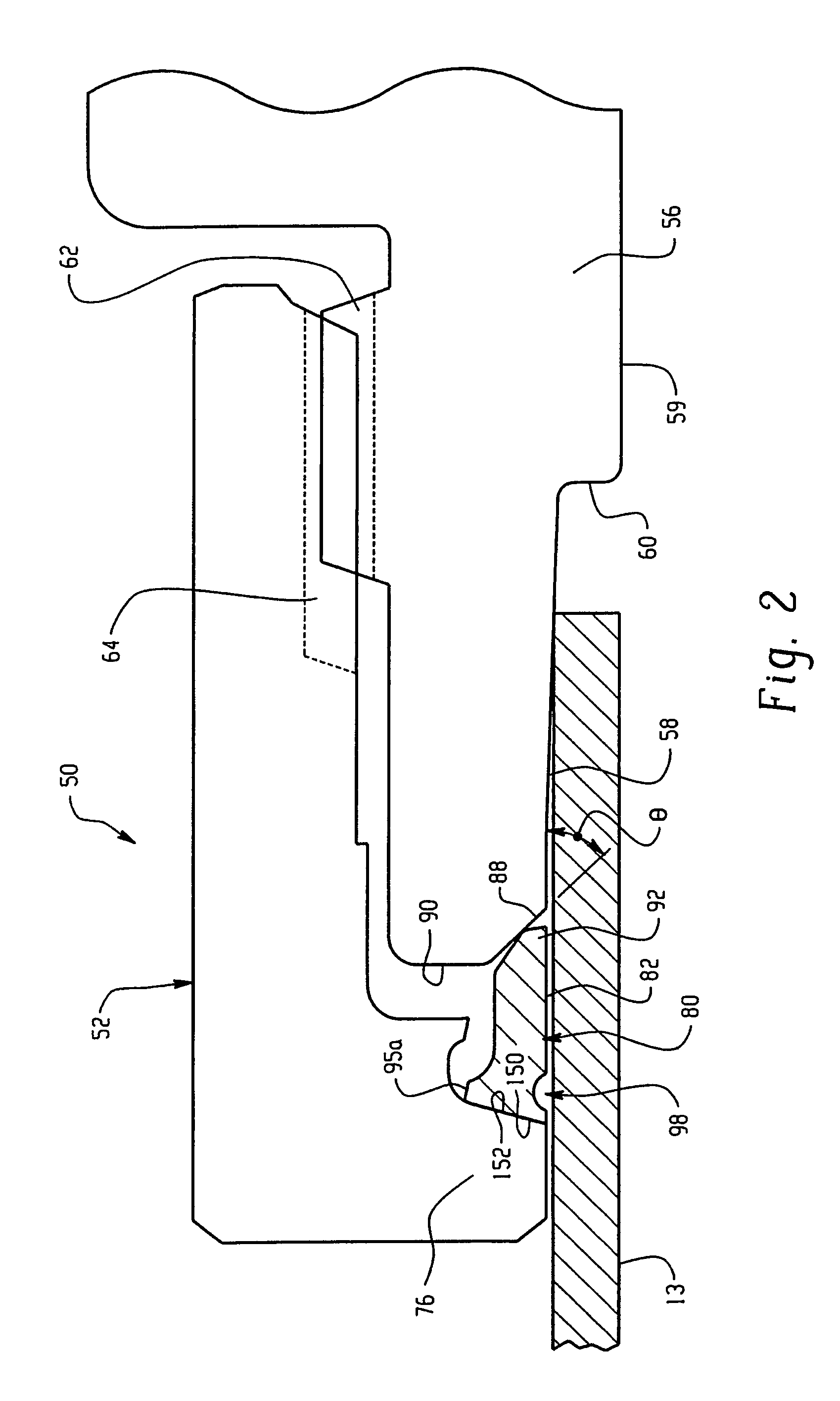
[0035]In accordance then with one aspect of the invention, a tube fitting is provided having a tube gripping device that initially is integral with one of the coupling elements and upon pull-up separates therefrom to function as a single ferrule fitting. In the preferred embodiment, the tube gripping device or ferrule is integrally formed with a female threaded nut and is attached thereto by a frangible thin web portion that breaks as the ferrule cams initially against a camming surface of the male threaded component. As a single ferrule after separation, the ferrule acts against the steep camming angle surface of a male threaded body. The steep camming surface angle is particularly advantageous when the hardness of the tube gripping device has a ratio of at least about 3.3 times and preferably at least 4 times the hardness of the tubing material on the Vickers scale.

[0036]Although a number of aspects of the invention are described herein as being incorporated into the exemplary emb...


PUM

PropertyMeasurementUnit
included angleaaaaaaaaaa
camming angleaaaaaaaaaa

Abstract

A tube fitting for a tube end has a female threaded member that cooperates with a male threaded member. The female member includes a tube gripping device in the form of a gripping ring or ferrule that is attached to the female member by a frangible web. Upon a partial pull-up the ferrule engages a camming surface on the male threaded member and breaks off or separates from the female threaded member to become a separate piece so that the fitting then functions as a single ferrule tube fitting. Additional features include a steep camming angle on the camming surface to cause the ferrule to grip the tube end with a bite-type action and to form a primary seal between the camming surface and a front end of the separated ferrule. The ferrule front end, and optionally the entire female threaded member including the initially integral tube gripping device, are hardened to have a hardness ratio that is at least about 3.3 times the hardness of the material of the tube end on the Vickers scale.

Description

RELATED APPLICATIONS[0001]This application is a continuation in part of co-pending U.S. national application Ser. No. 10 / 467,444 filed on Aug. 6, 2003 for TUBE FITTING WITH SEPARABLE TUBE GRIPPING RING, which is a national application from International patent application No. PCT / US02 / 03431 filed on Feb. 6, 2002 for TUBE FITTING WITH SEPARABLE TUBE GRIPPING RING, both of which claim the benefit of U.S. Provisional patent application Ser. No. 60 / 266,735 filed on Feb. 6, 2001 for TUBE FITTING WITH INTEGRAL NUT AND FERRULE, and Ser. No. 60 / 329,943 filed in Oct. 17, 2001 for TUBE FITTING, the entire disclosures all of which are fully incorporated by reference.TECHNICAL FIELD OF THE INVENTION[0002]The subject invention is generally directed to the art of fittings for pipe and tube. More particularly, the invention is directed to a flareless tube fitting that uses a tube gripping element that is initially joined to one of the coupling elements and separates therefrom during assembly onto ...

Claims


Application Information

Patent Timeline
Patent Type & Authority Patents(United States)
IPC IPC(8): F16L33/00F16L13/14F16L19/065F16L19/08F16L19/14
CPCF16L19/14F16L19/00F16L19/08F16L19/065
Inventor WILLIAMS, PETER C.BENNETT, MARK A.
Owner SWAGELOK CO
Why Eureka
Try Eureka