Two-dimensional small angle x-ray scattering camera

a small angle, x-ray scattering technology, applied in the field of x-ray scattering cameras, can solve the problems of low resolution, low flux of pinhole cameras, and one-dimensional cameras, and achieve the effect of large angular rang

Active Publication Date: 2006-11-21
OSMIC
View PDF16 Cites 20 Cited by
  • Summary
  • Abstract
  • Description
  • Claims
  • Application Information

AI Technical Summary

Benefits of technology

[0008]Some embodiments of the invention may have one or more of the following advantages. The camera can be used to investigate anisotropic material and can be configured into a high resolution reflectometer, or a high resoluti

Problems solved by technology

The Kratky camera has achieved high resolution, good flux and Qmin, but it is a one-dimensional camera and therefore suffers from smearing.
Although many de-smearing procedures have been developed, some amount of information is still unavoidably lost.
However, the pinhole camera has a low flu

Method used


Image

  • Two-dimensional small angle x-ray scattering camera
  • Two-dimensional small angle x-ray scattering camera
  • Two-dimensional small angle x-ray scattering camera

Examples


Embodiment Construction

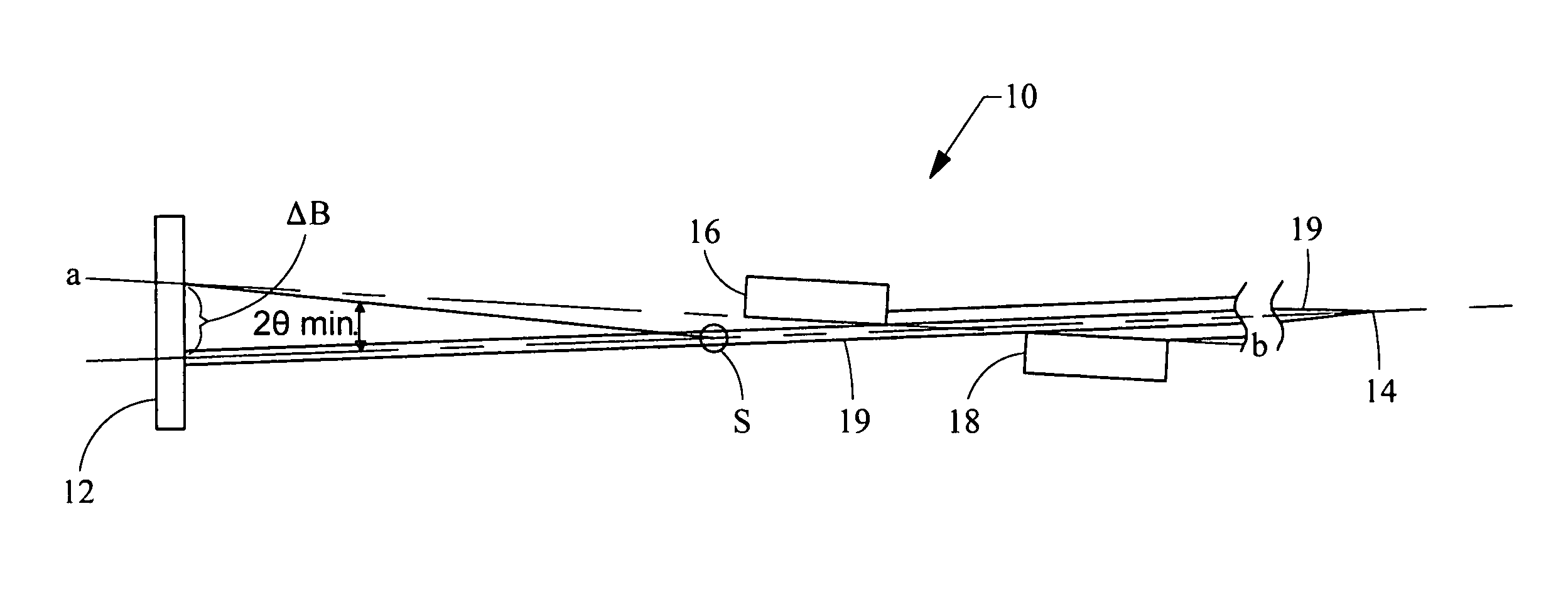
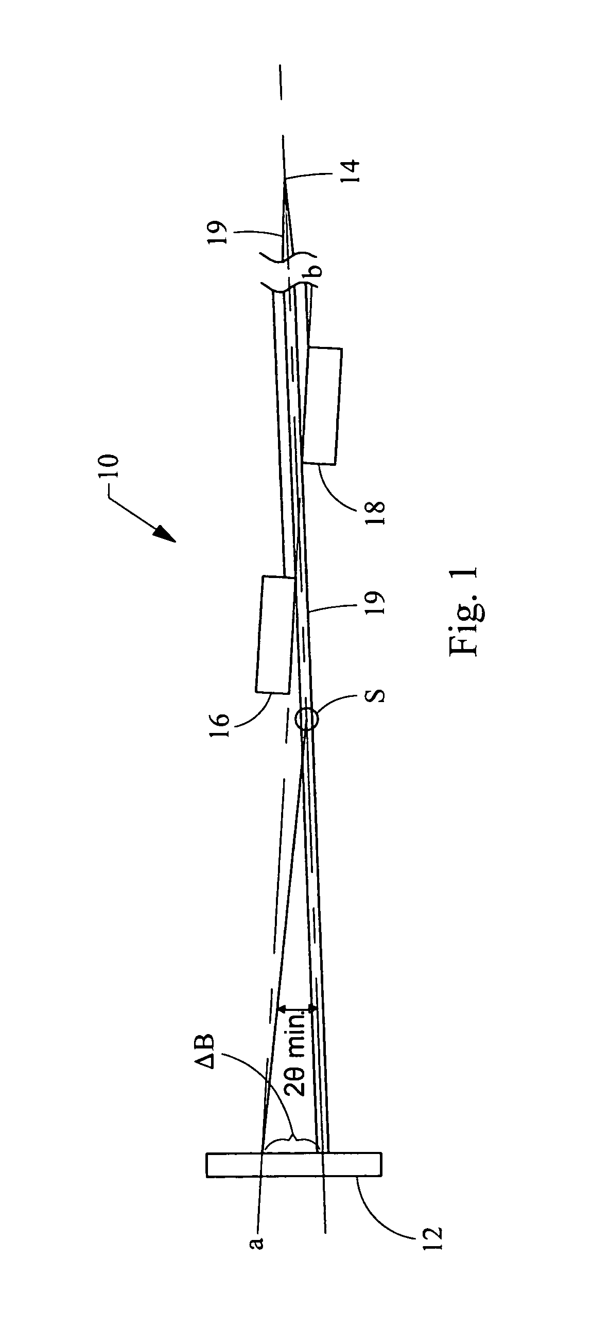
[0016]FIG. 1 depicts a Kratky camera 10 commonly used for small angle x-ray scattering. The camera 10 includes a detector 12 and an x-ray source 14. The x-ray source 14 is a one dimensional line source. X-rays are collimated by a pair of blocks 16 and 18 aligned in a common plane (i.e. the plane of the paper). The collimation blocks direct x-rays 19 at a sample (S), the scattering of which is captured by the detector 12. When the two blocks 16 and 18 are properly aligned, there is no parasitic scattering beyond the line extending between the points a-b.

[0017]A Ni filter can be employed to suppress Kβ radiation and soft continuous x-rays. The Kratky camera 10 has good flux and Qmin but the one-dimensional nature of the Kratky camera 10 makes it suitable for use with only isotropic samples. Moreover, the Kratky camera produces a scattered x-ray pattern that suffers from severe distortion know as smearing. Although many de-smearing routines have been proposed and implemented, some info...


PUM


Abstract

A two-dimensional x-ray scattering camera includes a source, an optic, a detector, and a pair of collimating blocks. The source emits x-ray beams that are reflected by the optic towards a sample. The detector detects scattering from the sample, the pair of collimating blocks is positioned between the optic and the detector to collimate the beam. A bottom surface of one block is substantially parallel a top surface of the other block, and the blocks are rotatable relative to the beam about a pivot. The system forms a two-dimensional beam that is symmetric about the primary beam axis at the detector position, regardless how the beam is collimated by the collimating blocks. The system therefore eliminates smearing and can be used for anisotropic small angle scattering at high resolution and low Qmin.

Description

BACKGROUND[0001]The present invention relates generally to an x-ray scattering camera, and more particularly relates to a two-dimensional x-ray scattering camera.[0002]In x-ray scattering, the performance of the camera is typically characterized by the flux, the resolution, defined as the beam diameter at the detector position divided by the sample-to-detector distance, and a parameter Qmin, defined as[0003]Qmin=4⁢πλ⁢sin⁢⁢θmin,where λ is the wavelength and θmin is the minimum access angle (i.e., the smallest angle, relative to the primary beam, at which meaningful scattering can be collected). In general, increasing the resolution of the system decreases the flux and Qmin, whereas increasing the flux decreases the resolution and Qmin.[0004]To address these issues, a camera known as a Kratky camera using a collimation block and an x-ray source in a line projection was developed. The Kratky camera has achieved high resolution, good flux and Qmin, but it is a one-dimensional camera and...

Claims


Application Information

Patent Timeline
IPC IPC(8): G01N23/201
CPCG01N23/20008G01N23/201G21K1/04G01N23/207
Inventor JIANG, LICAI
Owner OSMIC
Why Eureka
Try Eureka