Dynamic control system and method for multi-combustor catalytic gas turbine engine

a technology of dynamic control system and gas turbine engine, which is applied in the direction of burner control device, combustion type, combustion using catalytic material, etc., can solve the problems of catalyst overheating and catalytic activity loss in a very short time, and the application of industrial or otherwise, gas turbine engines with catalytic combustion,

Inactive Publication Date: 2006-12-26
KAWASAKI HEAVY IND LTD
View PDF81 Cites 95 Cited by
  • Summary
  • Abstract
  • Description
  • Claims
  • Application Information

AI Technical Summary

Problems solved by technology

The application of industrial, or otherwise, gas turbine engines with catalytic combustion, however, has been limited to the single-silo configuration.
Unfortunately, however, such systems may have a much more limited window of operation compared to conventional diffusion flame combustors.
For example, fuel/air ratios above a certa

Method used


Image

  • Dynamic control system and method for multi-combustor catalytic gas turbine engine
  • Dynamic control system and method for multi-combustor catalytic gas turbine engine
  • Dynamic control system and method for multi-combustor catalytic gas turbine engine

Examples


Embodiment Construction

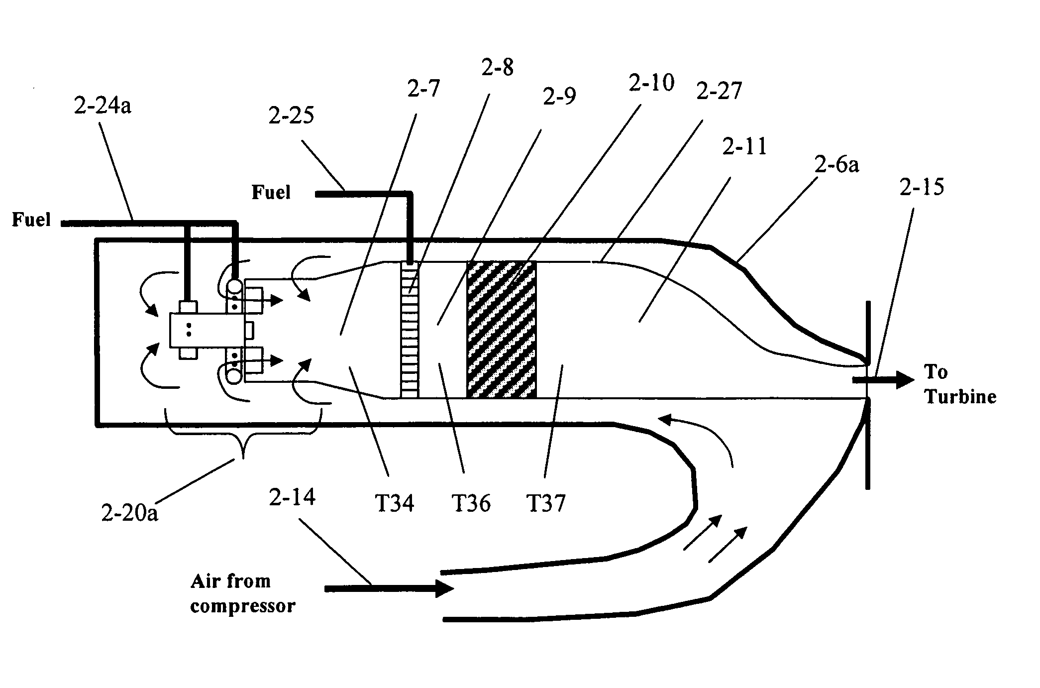
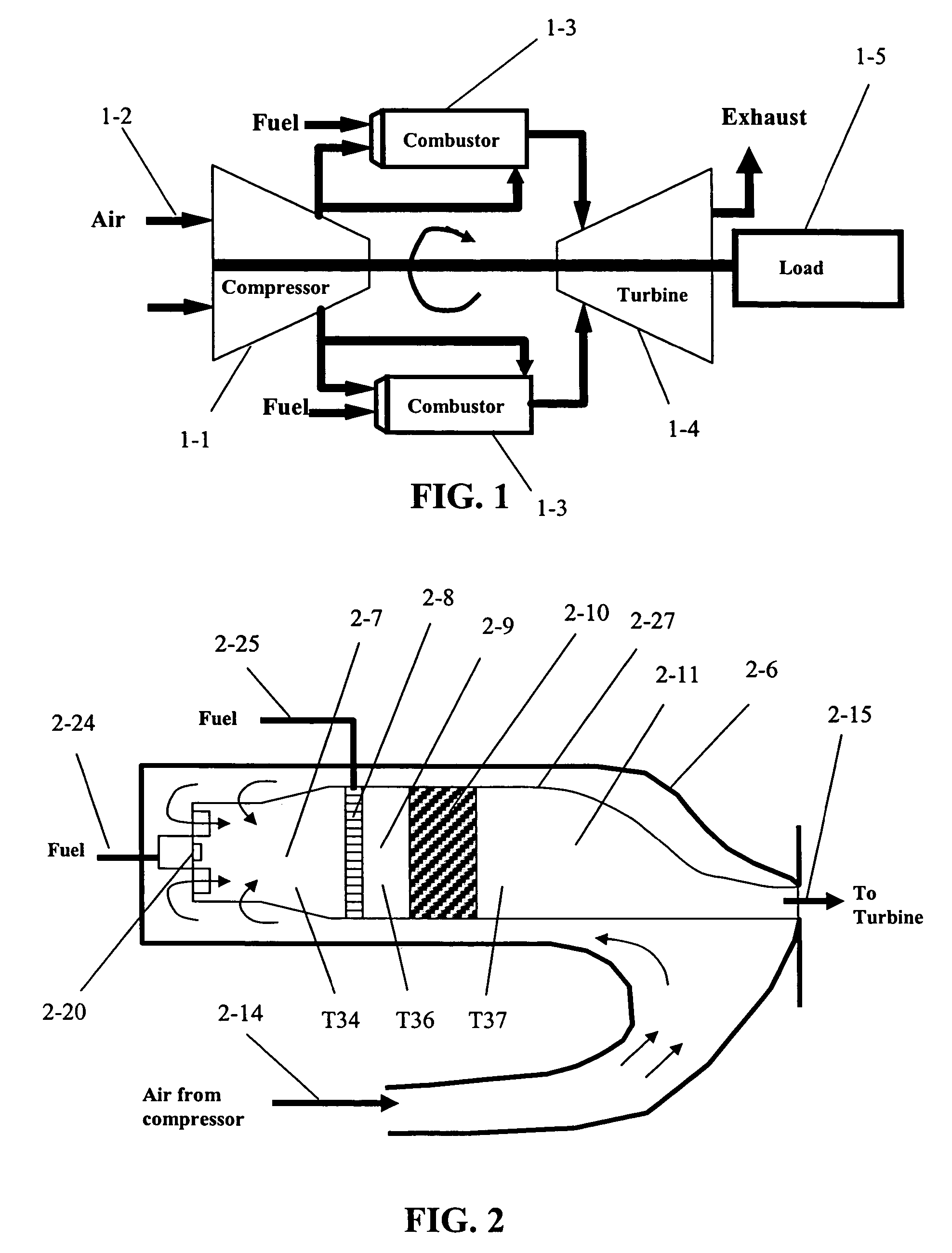
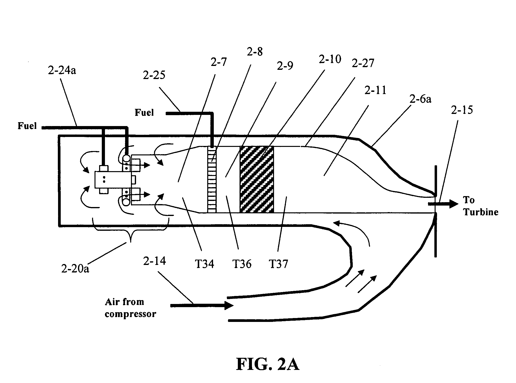
[0026]The present invention provides a catalytic multi-combustor system and associated methods of operation. The following description is presented to enable any person of ordinary skill in the art to make and use the invention. Descriptions of specific applications are provided only as examples. Various modifications to the exemplary embodiments will be readily apparent to those skilled in the art, and the general principles defined herein may be applied to other examples and applications without departing from the spirit and scope of the invention. Thus, the present invention is not intended to be limited to the examples shown, but is to be accorded the widest scope consistent with the principles and features disclosed herein.

[0027]Exemplary methods and systems are described herein for improved control strategies for an efficient application of multi-combustor catalytic combustion system configurations for gas turbine engines. Various methods described herein address issues relati...


PUM


Abstract

According to one aspect, a method of controlling a multi-combustor catalytic combustion system is provided for determining a characteristic of a fuel-air mixture downstream of a preburner associated with a catalytic combustor and adjusting the fuel flow to the preburner based on the characteristic. The characteristic may include, for example, a measurement of the preburner or catalyst outlet temperature or a determination of the position of the homogeneous combustion wave in the burnout zone of the combustor.

Description

CROSS REFERENCE TO RELATED APPLICATION[0001]The present application claims benefit of earlier filed provisional patent application, U.S. application Ser. No. 60 / 440,940, filed on Jan. 17, 2003, and entitled “DYNAMIC CONTROL SYSTEM AND METHOD FOR MULTI-COMBUSTOR CATALYTIC GAS TURBINE ENGINE,” which is hereby incorporated by reference as if fully set forth herein.BACKGROUND[0002]1. Field of the Invention[0003]The invention relates generally to combustion control systems, and more particularly to dynamic control systems and methods for use with multi-combustor processes as they relate to and are utilized by gas turbine engines with catalytic combustors.[0004]2. Description of the Related Art[0005]In a conventional gas turbine engine, the engine is controlled by monitoring the speed of the engine and adding a proper amount of fuel to control the engine speed. Specifically, should the engine speed decrease, fuel flow is increased causing the engine speed to increase. Similarly, should th...

Claims


Application Information

Patent Timeline
IPC IPC(8): F02C9/00F23R3/40F23C13/00
CPCF23C13/00F23C13/02F23R3/40F23C2900/13002F23D2208/10F23N2037/12F23N2041/20F23N2237/12F23N2241/20
Inventor YEE, DAVID K.REPPEN, DAG
Owner KAWASAKI HEAVY IND LTD
Why Eureka
Try Eureka