Three-phase rectifier

Inactive Publication Date: 2007-03-06
DAIKIN IND LTD
View PDF10 Cites 17 Cited by
  • Summary
  • Abstract
  • Description
  • Claims
  • Application Information

AI Technical Summary

Benefits of technology

[0012]When the three-phase rectifier of claim 1 is employed, a phase of an input current can be advanced by flowing a resonance current to the low frequency filter, consequently lowering in input power factor and lowering in DC voltage are prevented from occurrence, because the low frequency filter is connected between the three phase power source and the diode rectification circuitry. Of course, higher harmonic currents are reduced to be equal to or less than standard values by the AC reactors.
[0013]When the three-phase rectifier of claim 2 is employed, a high input power factor is maintained in addition to the operation and effect of claim 1, because the % impedance of each of the AC reactors is determined to be equal to or greater than 12% and equal to or less than 36%.
[0014]When the three-phase rectifier of claim 3 is employed, a high input power factor is maintained in addition to the operation and effect of claim 1, because the inductance value of each of the AC reactors is determined to be equal to or greater than (V/400)2×10 m H (where, V is a voltage of the three-phase power supply) and equal to or less than (V /400)2×

Problems solved by technology

When the three-phase rectifier having the arrangement illustrated in FIG. 19, disadvantages arise in that reactors each having a larger inductance value to some degree are needed to satisfy a higher harmonics standard (standard applied to devices input currents of which is equal to

Method used


Image

  • Three-phase rectifier
  • Three-phase rectifier
  • Three-phase rectifier

Examples


Embodiment Construction

[0037]Hereinafter, referring to the attached drawings, we explain three-phase rectifier of embodiments according to the present invention in detail.

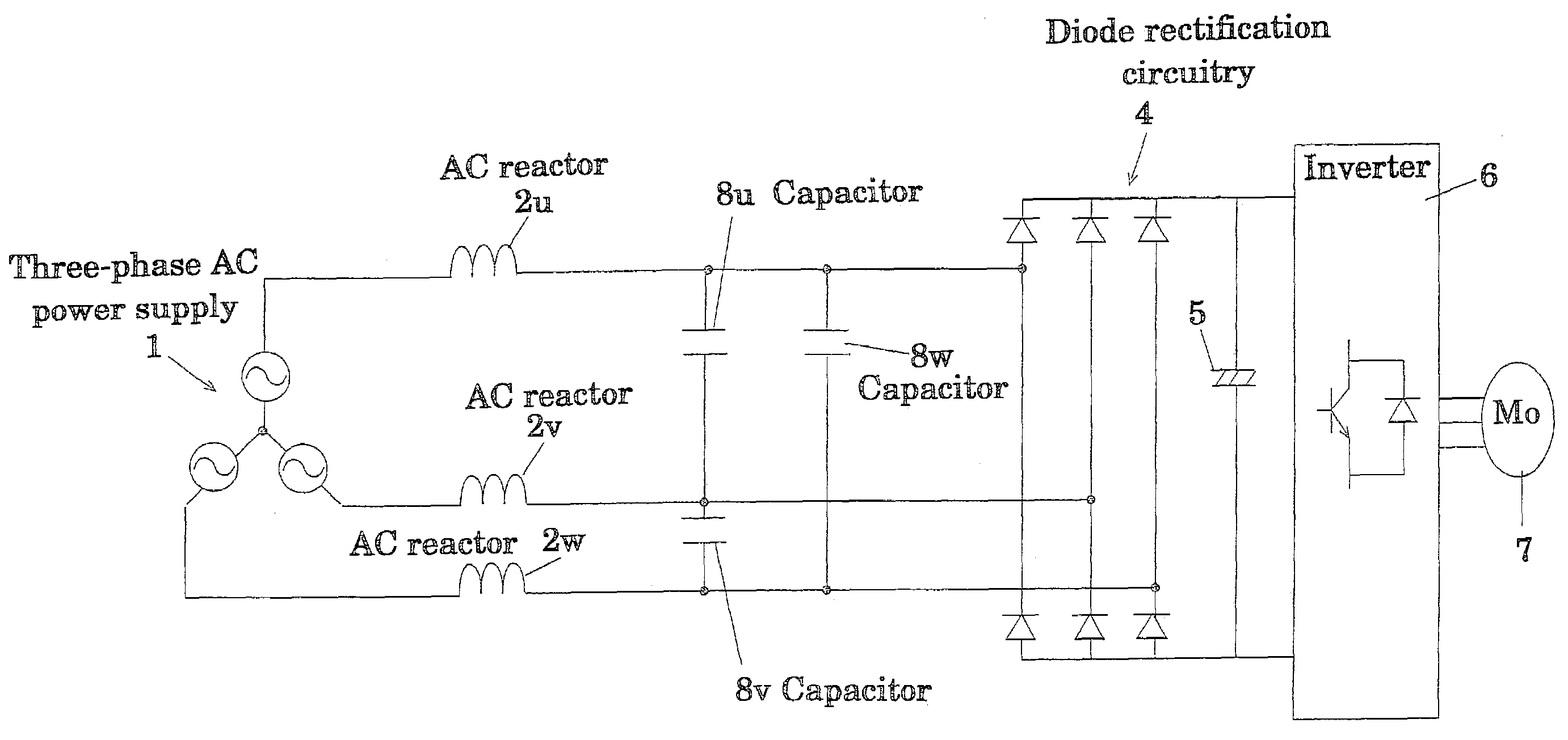
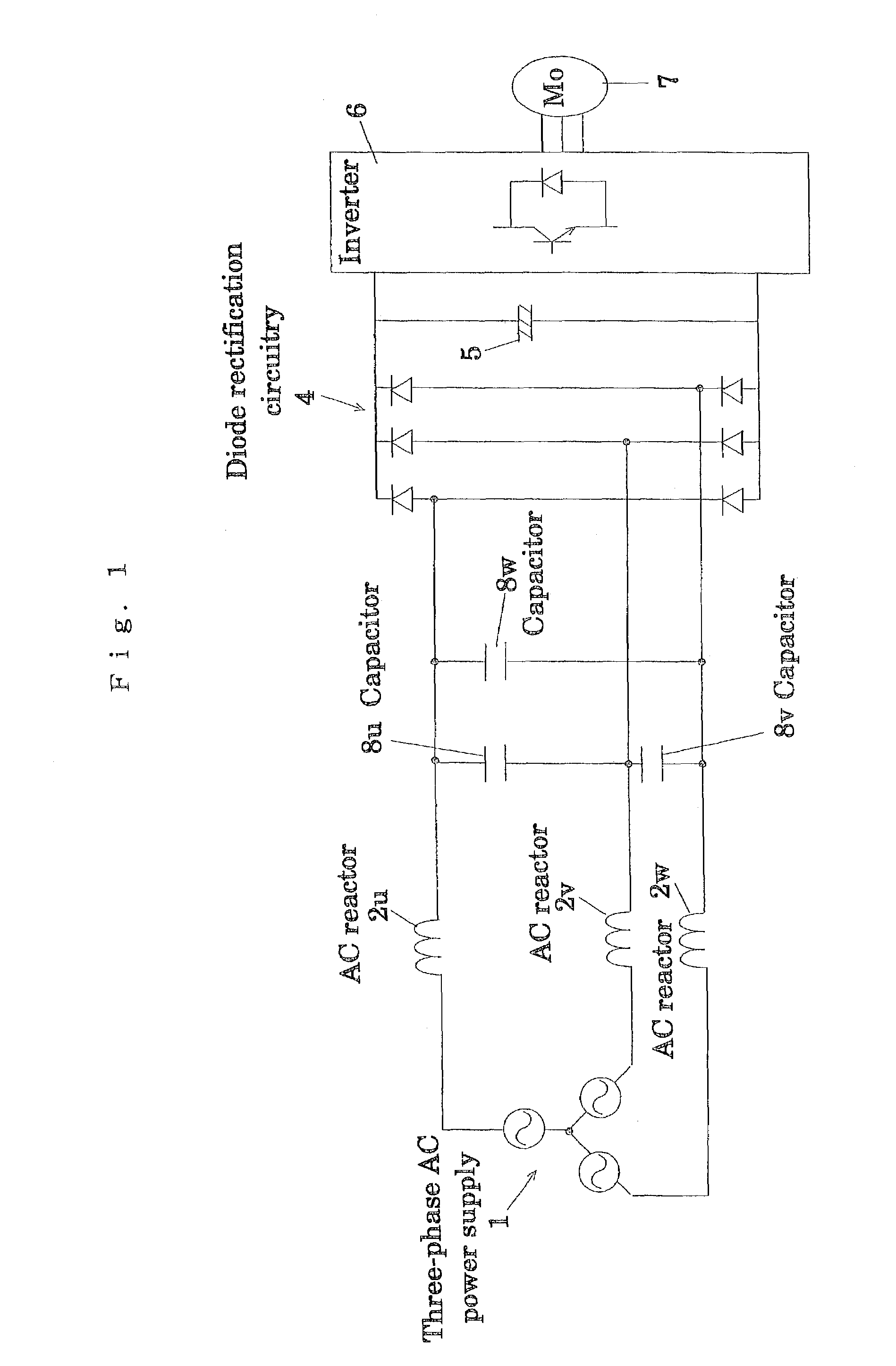
[0038]FIG. 1 is an electric circuit diagram illustrating an embodiment of a three-phase rectifier according to the present invention.

[0039]In this three-phase rectifier, each one terminal of AC reactors 2u, 2v and 2w is connected to a terminal of each phase 1u, 1v and 1w of a three-phase AC power supply 1. Each the other terminal of the AC reactors 2u, 2v and 2w is connected to each input terminal of a diode rectification circuitry 4. A smoothing capacitor 5 and an inverter 6 are connected in parallel to one another between output terminals of the diode rectification circuitry 4. And, each of capacitors (filter capacitors) 8u, 8v and 8w is connected between lines, each being between each of the other terminals of the AC reactors 2u, 2v and 2w and each of the input terminals of the diode rectification circuitry 4. Also, an output from the...


PUM


Abstract

A capacitor-input type three-phase rectification circuit comprises a three-phase AC power supply (1), a diode rectifier circuit (4), and a low-frequency filter connected between the three-phase AC power supply (1) and the diode rectification circuitry (4), the low frequency filter consisting of AC reactors (2u)(2v)(2w) and Δ-connection or Y-connection capacitors (8u)(8v)(8w), so that higher harmonic currents are reduced to be equal to or less than standard values, and that lowering in input power factor and lowering in DC voltage are prevented from occurrence.

Description

FIELD OF TECHNOLOGY[0001]This invention relates to improvement of a three-phase rectifier.RELATED ART[0002]Conventionally, trial of reduction in higher harmonics currents is proposed by connecting AC reactors or DC reactors, as shown in FIG. 19, in a three-phase rectifier of capacitor input type. Specifically, a common mode filter, AC reactors, and a diode rectifying circuit are connected to a three-phase power supply in this order, a smoothing capacitor is connected between output terminals of the diode rectifying circuit and an inverter is connected in parallel to the smoothing capacitor. Further, an output of the inverter is supplied to a motor.[0003]When the three-phase rectifier having the arrangement illustrated in FIG. 19, disadvantages arise in that reactors each having a larger inductance value to some degree are needed to satisfy a higher harmonics standard (standard applied to devices input currents of which is equal to or less than 16 A per phase), and that lowering in i...

Claims


Application Information

Patent Timeline
IPC IPC(8): H02M7/00H02M5/45H02M1/12H02M7/06H02M1/42H02M1/44H02M7/12H02M7/48
CPCH02M1/126H02M1/4216H02M1/44H02M1/4266Y02B70/123Y02B70/10
Inventor KAWASHIMA, REIJISAKAKIBARA, KENICHIKAGIMURA, SUMIOTANATSUGU, ISAO
Owner DAIKIN IND LTD
Why Eureka
Try Eureka