Variation of power levels within an LED array

a technology of power levels and led arrays, applied in semiconductor devices, lighting and heating apparatus, lighting support devices, etc., can solve the problems of insufficient lumens or candlepower, leds are not without problems, and are highly susceptible to damag

Inactive Publication Date: 2007-05-15
PHAROS MARINE AUTOMATIC POWER
View PDF24 Cites 22 Cited by
  • Summary
  • Abstract
  • Description
  • Claims
  • Application Information

AI Technical Summary

Problems solved by technology

As a result, they are highly susceptible to damage due to temperature variations and vibrations.
However, LEDs are not without their problems.
A first problem is that typical low output 5 millimeter LEDs (currently available in lighting devices such as those used for marine and airport safety lights) only have a driving current ranging from about 50 to 70 milliwatts and put out insufficient lumens or candlepower to meet the 3–4 mile visibility requirement.
Although it is possible to increase the optical output considerably by increasing the forward current above the nominal rated value, such an increase in forward current generally leads to premature failure due to overheating of the diode junction.
A second problem is that LEDs have a poorly directed, non-uniform and excessively divergent pencil beam pattern.
While this provides an omni-directional beam pattern, lacking further optical enhancement, the result is energy inefficient and grossly non-uniform in horizon intensity.
Marine LED lanterns use multiple arrays of numerous LEDs that do not have a single point source of light and cannot use a fresnel lens to capture and focus the light from the LED arrays used.

Method used


Image

  • Variation of power levels within an LED array
  • Variation of power levels within an LED array
  • Variation of power levels within an LED array

Examples


Embodiment Construction

[0050]One embodiment of the present invention relates to a lighting device using high flux light emitting diodes (LEDs) mounted on a heat sink in a conventional fresnel lens having a diffuser positioned between the LEDs and the fresnel lens. High flux LEDs are defined herein as LEDs with driving current of about 1–5 Watts and having a high output of lumens. This embodiment is described below.

[0051]Referring now to the drawings, it is noted that like reference characters designate like or similar parts throughout the drawings. The figures, or drawings, are not intended to be to scale. For example, purely for the sake of greater clarity in the drawings, wall thicknesses and spacings are not dimensioned as they actually exist in the assembled embodiments.

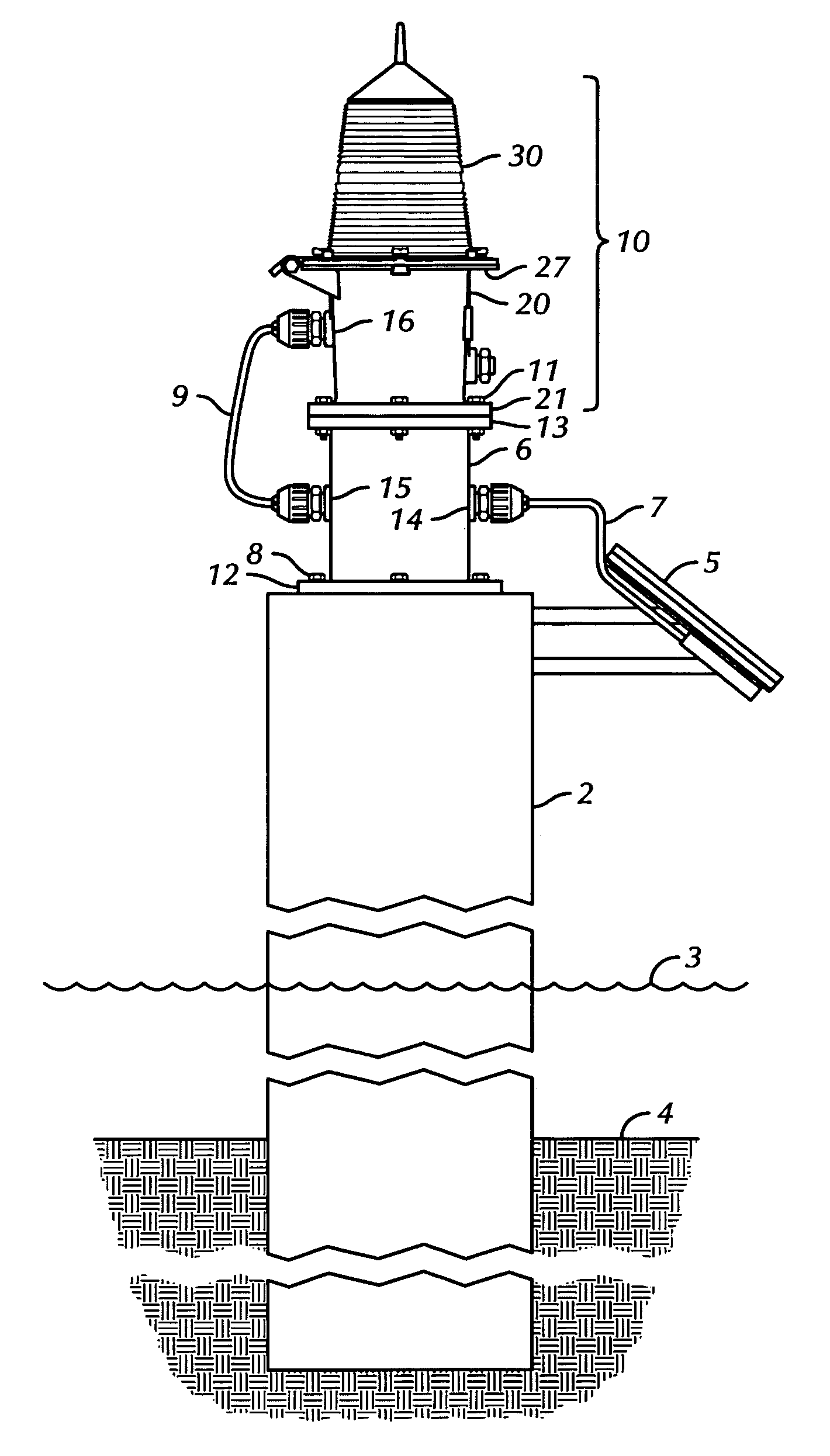
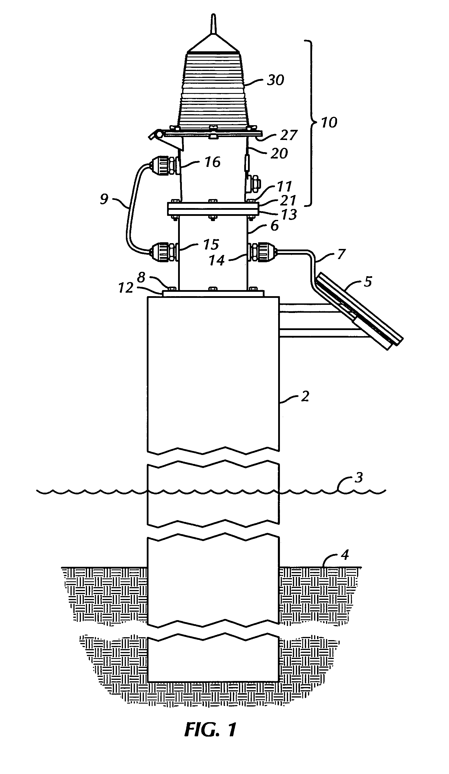
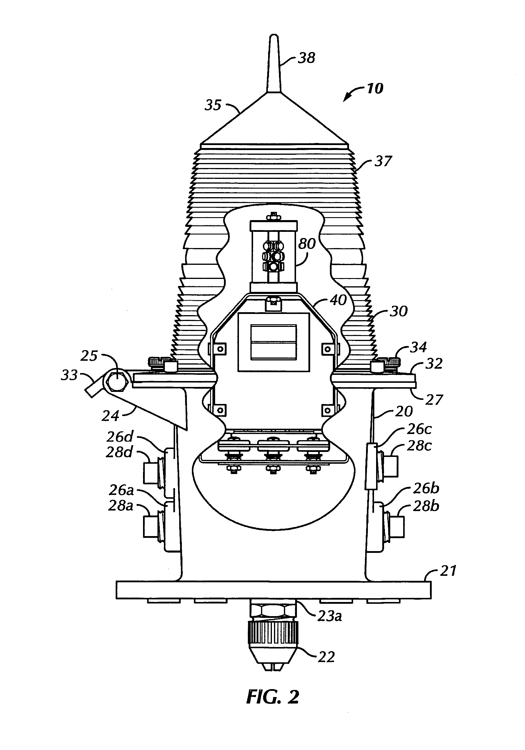
[0052]Several embodiments of the lighting device of the present invention are described in detail below. One preferred embodiment of a lighting device 10 of the present invention, shown in FIGS. 1 and 2, is often installed on bridges, ...


PUM


Abstract

A lighting device having a plurality of high flux LEDs mounted on a heat sink and surrounded by a diffuser and a power supply that provides independent power to individual sets of the LEDs. The heat sink serves to transfer heat from the LEDs to the outside environment. In one embodiment the lighting device is positioned within a fresnel lens to produce a distribution of light.

Description

CROSS REFERENCE TO RELATED APPLICATIONS[0001]This application claims priority to pending U.S. patent application Ser. No. 60 / 629,856, filed Nov. 20, 2004 by inventors Stephen E. Trenchard and Alan Trojanowski and entitled “Variation of Power Levels within an LED[0002]This application for patent is related to pending U.S. patent application Ser. No. 10 / 695,191, filed Oct. 28, 2003 by inventors Stephen E. Trenchard and Alan Trojanowski and entitled “High Flux LED Lighting Device.”BACKGROUND OF THE INVENTION[0003]1. Field of the Invention[0004]The present invention relates generally to a lighting device having high flux light emitting diodes, or LEDs, mounted on a heat sink and surrounded by a diffuser. The present invention further relates to an LED assembly having multiple layers of LEDs mounted on a heat sink and surrounded by a diffuser, wherein the LED assembly is positioned within a fresnel lens and individual power is provided to each layer of LEDs.[0005]2. Description of the Re...

Claims


Application Information

Patent Timeline
Patent Type & Authority Patents(United States)
IPC IPC(8): F21V29/00
CPCF21V5/045F21V31/04F21W2111/043F21Y2101/02F21K9/135F21K9/232F21Y2115/10
Inventor TRENCHARD, STEPHEN E.TROJANOWSKI, ALAN
Owner PHAROS MARINE AUTOMATIC POWER
Why Eureka
Try Eureka