Image output device, image forming device and method for generating video hard copy

a technology of image output device and image forming device, which is applied in the direction of digital output to print units, visual presentations, instruments, etc., can solve the problems of response delay time and difficulty in us

Inactive Publication Date: 2007-05-22
PANASONIC CORP
View PDF10 Cites 20 Cited by
  • Summary
  • Abstract
  • Description
  • Claims
  • Application Information

AI Technical Summary

Benefits of technology

[0011]In view of the foregoing, it is an object of this invention to provide an image output device and so forth that by which a user can select the image that he wants to print with reliability in the case of producing a hard copy of a video (a moving picture) of television broadcast and so forth displayed on a monitor screen. Further, it is also an object of this invention to provide the image output device and so forth that can display the video (the moving picture) that is broadcast in real time continuously without interruption while an image is being printed.
[0013]As a result, since the present device holds at least two frame images that are n frames apart and displays these frame images that are held, the user can select the image that is closer to the timing he wants, considering n frames' time from confirming the image he wants to print to executing a print instruction.
[0019]As a result, the present device displays the first frame image, the frame images that are n frames and m frames apart from the first frame image, respectively, that are updated and held, the user can see the real time images without interruption and, at the same time, can select the image he wants more to print between the images that are n frames and m frames apart from the latest frame images.
[0021]As a result, since the present device enables the user to change the values of n and m that are print timing coefficients, he can set more suitably a selection timing of the image that he wants to print by changing the values of n and m as necessary.
[0023]As a result, since the present device presents to the user the video that can distinguish each frame image in advance to the initial values of the print timing coefficients, n and m, and changes the values of n and m more suitably using this video, it is not necessary for the user to repeat modifications to determine the appropriate values of n and m.

Problems solved by technology

However, conventionally, in the case that the user gives a print instruction while he is watching the monitor screen of a television receiver, from the time the user captures the image by vision that he wants to print to the time he instructs to print, response delay time occurs generally, and therefore, an image later than the image he wants to print is printed and it is very irksome.
As is described above, in the case of printing using the conventional analogue video printer, since the image that the user does not want is printed and the video (the moving images) is discontinued, it is difficult to use.

Method used


Image

  • Image output device, image forming device and method for generating video hard copy
  • Image output device, image forming device and method for generating video hard copy
  • Image output device, image forming device and method for generating video hard copy

Examples


first embodiment

The First Embodiment

[0041]A video output device 10 according to the present embodiment captures image data of a video displayed on a television (hereafter, referred to as “TV”) receiver and so forth and produces a hard copy based on the image data. Moreover, hereafter, “video” means moving images displayed on a monitor screen by TV broadcast, computer graphics and so forth.

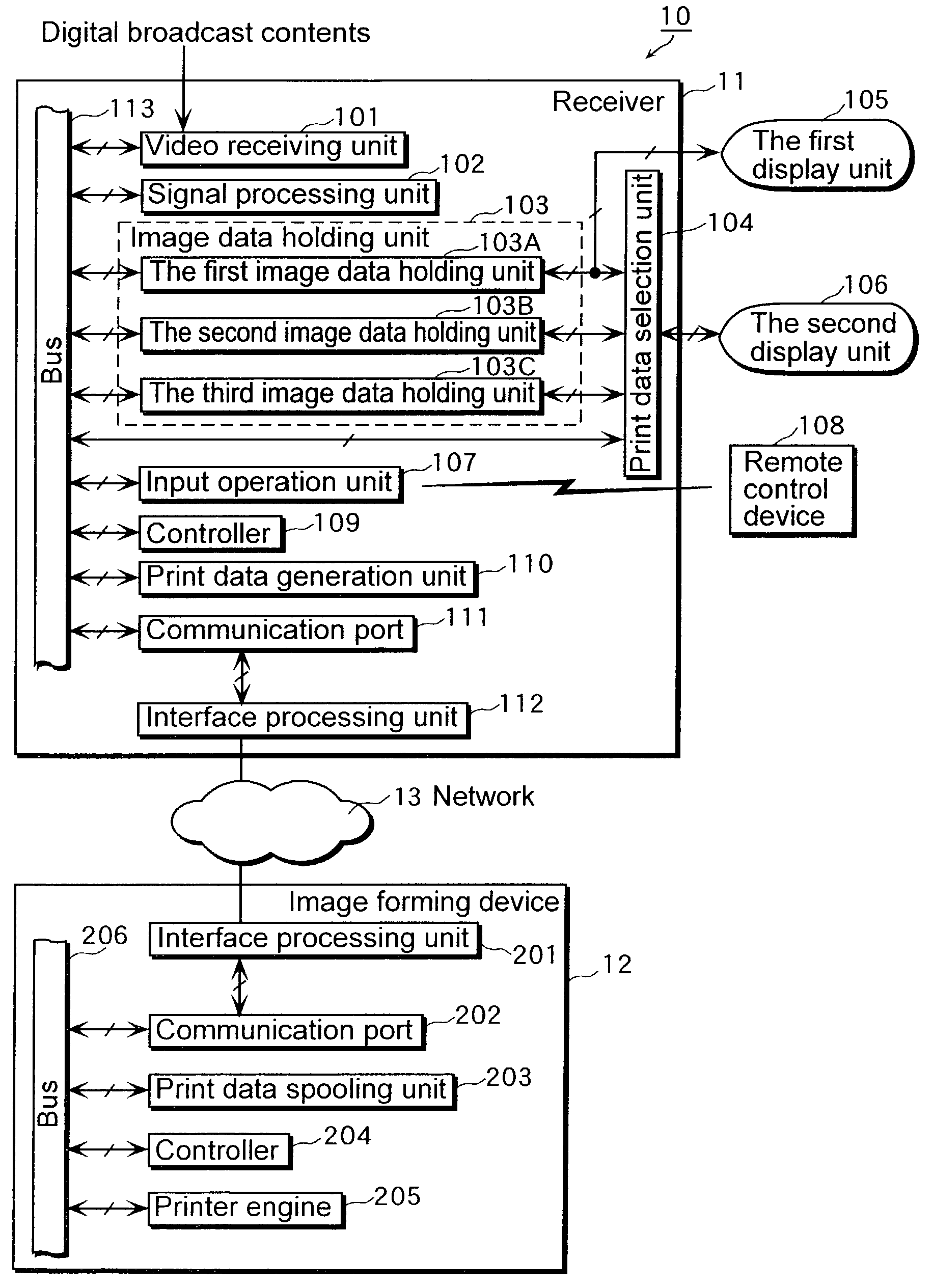
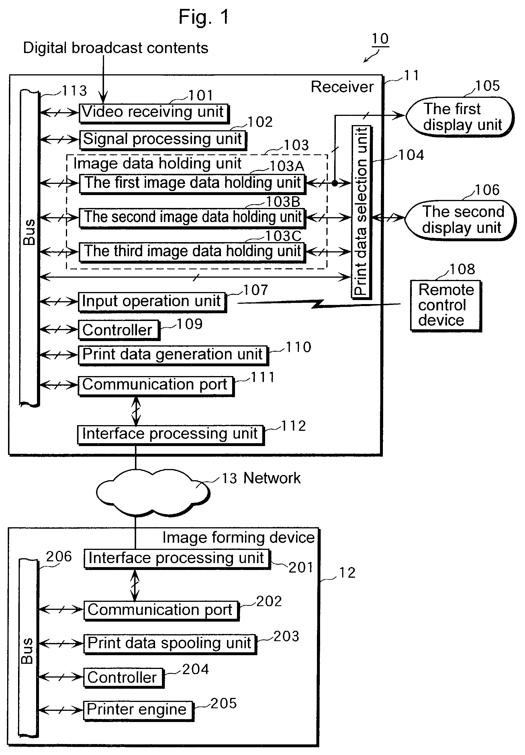
[0042]FIG. 1 is a block diagram that shows functional structures of a receiver 11 and an image forming device 12 that constitute the image output device 10.

[0043]The receiver 11 is a device that receives TV broadcast waves and so forth transmitted by terrestrial broadcasting, BS (Broadcasting Satellite), CS (Communication Satellite) and so forth, and comprises a video reception unit 101, a signal processing unit 102, an image data holding unit 103, a print data selection unit 104, a first display unit 105, a second display unit 106, an input operation unit 107, a remote control device 108, a controller 109, a prin...

second embodiment

The Second Embodiment

[0107]In the first embodiment, a practical example in which the receiver includes the second display unit, the second and the third image data holding units is indicated, but in the second embodiment, a practical example in which the image forming device includes the second display unit, the second and the third image data holding units is indicated.

[0108]FIG. 7 is a block diagram that shows functional structures of a receiver 21 and a image forming device 22 that constitute an image output device 20 according to the second embodiment.

[0109]The different points between the structure shown in FIG. 7 and the structure shown in FIG. 1 are that, as is stated above, the receiver 21 according to the second embodiment does not include the second image data holding unit 103B, the third image data holding unit 103C, the print data selection unit 104, the second display unit 106 and the print data generation unit 110 in the receiver 11 according to the first embodiment an...

third embodiment

The Third Embodiment

[0142]In the third embodiment, operations of a remote control device to instruct printing according to the image output device 10 are explained referring to FIG. 9 and FIG. 10.

[0143]FIG. 9 is an external view of the remote control device 108 according to the present embodiment and FIG. 10 is a diagram that shows the relationship between two frame images identified by receiving an instruction to print from the user and operations of the remote control device 108.

[0144]For a start, until the user pushes down a printing multiple button 601, the image data are continuously updated in the second image data holding unit 103B and the third image data holding unit 103C. This state is a state waiting for an input from the user 701.

[0145]Next, when the user pushes down the printing multiple button 601 once (let this time be the time T1 in FIG. 3), the update of the second image holding unit 103B and the third image holding unit 103C stops and two frame images are identifie...


PUM


Abstract

A video buffer that updates and holds an inputted video signal by a unit of a frame image includes: an image data holding unit having a first image data holding unit that holds the latest frame image, a second image data holding unit that holds a second frame image that goes back n pieces of frames in time from the first frame image and a third image data holding unit that holds the third frame image that goes back m pieces of frames in time from the first frame image; a moving picture display unit that displays the latest frame image held in the first image data holding unit; a print data selection unit that selects a frame image stored in any of the first to third image data holding units as a print object; a print confirmation display unit that displays the selected frame image; a print data generation unit that converts the image data of the displayed image into print data and so forth.

Description

BACKGROUND OF THE INVENTION[0001](1) Field of the Invention[0002]The present invention relates to an image output device, an image forming device and method for generating a video hard copy to print a video (moving images) displayed on a monitor screen and especially to technology that identifies suitably one image to be printed.[0003](2) Description of the Prior Art[0004]Conventionally, as for a method for producing a hard copy of a video (moving images) displayed on a monitor screen of a television receiver, there is a method for using an analogue video printer.[0005]This analogue video printer is connected with a television receiver and is provided with the same signal as an analogue video signal provided to a monitor screen of the television receiver. This analogue video signal is digitized in the analogue video printer and is recorded as image data in frame memory in the analogue video printer in sequence similarly to an image displayed in the monitor screen in a unit of frame....

Claims


Application Information

Patent Timeline
Patent Type & Authority Patents(United States)
IPC IPC(8): G06F15/00H04N1/00
CPCH04N1/00291H04N1/00294H04N2201/0039
Inventor TAKAMINE, KOUICHIHIROSE, ATSUSHI
Owner PANASONIC CORP
Why Eureka
Try Eureka