Control Method of a Printer, Program, and Recording medium

a control method and printer technology, applied in the direction of instruments, visual presentations, computing, etc., can solve the problems of inability to achieve the same, difficulty in setting equal top and bottom margins, and inability to find technology enabling the same in the literatur

Active Publication Date: 2017-02-09
SEIKO EPSON CORP
View PDF1 Cites 3 Cited by
  • Summary
  • Abstract
  • Description
  • Claims
  • Application Information

AI Technical Summary

Benefits of technology

[0009]The invention relates to a printer that enables the user to intuitively adjust the print layout while preventing unnecessarily executing an offset position compensation process appropriately to the operating mode of the printer, and further relates to a program and a recording medium.

Problems solved by technology

Because the top margin UM and the bottom margin DM must be different lengths in order to desirably center the target print area E3 in the label area E2, setting equal top and bottom margins is difficult and the margin settings are unintuitive for the user.
Switching between applying a compensation process or not according to the operating mode of the printer is therefore desirable, but technology enabling the same is not found in the literature.

Method used


Image

  • Control Method of a Printer, Program, and Recording medium
  • Control Method of a Printer, Program, and Recording medium
  • Control Method of a Printer, Program, and Recording medium

Examples


embodiment 1

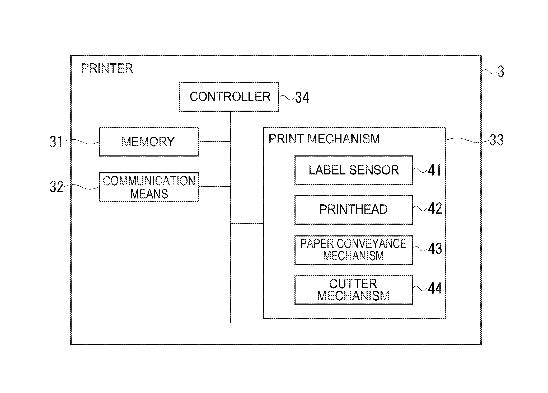
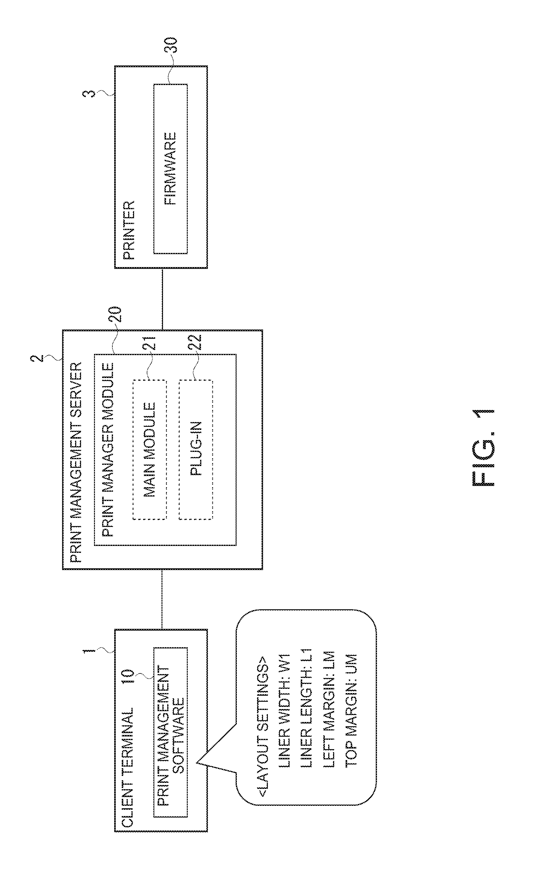
[0038]A control method of a printer, a program, and a recording medium according to the invention are described below with reference to the accompanying figures. In this embodiment, the control method (program) of a printer according to the invention is embodied by a plug-in 22 in a print manager module 20 of a print management server 2.

[0039]FIG. 1 illustrates the system configuration of a printing system SY according to an embodiment of the invention. The printing system SY includes a client terminal 1, print management server 2, and printer 3. The client terminal 1 and the print management server 2 are communicatively connected, and the print management server 2 and the printer 3 are communicatively connected. Note that wireless or wired connections may be used. The client terminal 1, print management server 2, and printer 3 may also be connected through the Internet or other network. Yet further, there may be multiple client terminals 1 and multiple printers 3 in the printing sy...

example 4

[0064]The print data coordinate system of the printer 3 in the foregoing first embodiment describes an example in which the leading edge of each unit print area E1 in the paper conveyance direction is coincident with the leading edge of each label area E2 (unit print area E1-2 in FIG. 4), but this embodiment of the invention can also be applied when the trailing end of the unit print area E1 in the paper conveyance direction is coincident with the trailing end of the label area E2. In other words, the invention can also be used when the leading end of each unit print area E1 and the leading end of each label area E2 are coincident in the reverse conveyance direction (first direction). In this configuration, the layout generator 54b generates the second layout information by moving the position of the target print area E3 relative to the unit print area E1 in the conveyance direction 1 / 2 of label gap G1 in the reverse conveyance direction (first direction) from the position in the fi...

embodiment 2

[0065]A second embodiment of the invention is described next with reference to FIG. 7 and FIG. 8. In the first embodiment, the layout generator 54b generates second layout information with a different top margin UM than the first layout information. This embodiment of the invention applies a process that deletes part of the top margin UM. This resolves problems that may occur when a conveyance problem, such as the paper slipping, occurs.

[0066]For example, as shown in FIG. 13, when the paper slips, for example, and the leading end of label B is detected before the process of printing (indicated by shading 101 in the figure) to the unit print area E1 where label A is printed ends, the leading end of label B is discarded and the next printing process (indicating by shading 102) starts triggered by detecting the leading end of label C. This results in a label 7 (label B in the example in the figure) that is mostly blank, and the label 7 being wasted. To resolve this problem, the plug-in...


PUM


Abstract

The user can configure the print layout intuitively, and prevent needlessly executing a compensation process based on the printer mode. A plug-in 22 that controls a printer 3 that prints to a target print area in each unit print area disposed in the conveyance direction of a continuous print medium has: a mode selector 51 that determines if the printer 3 prints based detecting each unit print area of the print medium; a layout acquisition unit 53b that acquires first layout information representing the location of the target print area in the unit print area; and a layout generator 54b that generates second layout information which differs from the first layout information in the conveyance direction of the print medium when the printer determines to print based on the position detection.

Description

BACKGROUND[0001]1. Technical Field[0002]The present invention relates to a control method of a printer including a process of adjusting the printing position of the print data, and further relates to a program and a recording medium.[0003]2. Related Art[0004]JP-A-2013-156710 describes related technology. More specifically, JP-A-2013-156710 discloses technology for determining the model of printer, paper size, and paper orientation, and adjusting the point of origin for printing the print data based on the results. As a result, this configuration can produce the desired printout even when the point of origin used by the client terminal (the printer driver that generates the print data) differs from the point of origin used by the printer.[0005]Some printers can also be used with multiple types of print media by changing a mode setting. For example, receipt printers that can be used with both continuous paper (print media used for producing receipts), and label roll paper (print media...

Claims


Application Information

Patent Timeline
Patent Type & Authority Applications(United States)
IPC IPC(8): G06K15/02
CPCG06K15/1885G06K15/024G06K15/022
Inventor YAMADA, YUSUKESUGIYAMA, KATSUHIKO
Owner SEIKO EPSON CORP
Why Eureka
Try Eureka