Radio reception system that inhibits transmission of acknowledgment or negative acknowledgment signal for a data channel when control information of a control channel exceeds a reception capability of a receiver

a radio reception system and control channel technology, applied in the field of reception apparatus and reception method, can solve the problems of inability to accurately decode data, inability to demodulate and decode data on a data channel using wrong control information, and inability to ensure data confidentiality

Inactive Publication Date: 2007-04-03
PANASONIC CORP
View PDF18 Cites 56 Cited by
  • Summary
  • Abstract
  • Description
  • Claims
  • Application Information

AI Technical Summary

Benefits of technology

[0010]It is an object of the present invention to provide a reception apparatus and reception method capable of preventing execution of reception, demodulation and decoding on a data channel using wrong control information.

Problems solved by technology

However, conventional reception apparatus 8 as described above has such a problem that when the control channel determination misidentifies a control channel not for reception apparatus 8 as a control channel for reception apparatus 8, reception, demodulation and decoding on a data channel is carried out using wrong control information.
Further, when data channel signals are properly decoded accidentally using wrong control information, data to a reception apparatus except reception apparatus 8 is received, and there arise problems with inconsistency of data and confidentiality.
Furthermore, in a communication system using so-called hybrid ARQ (Automatic Repeat reQuest), when reception, demodulation and decoding on a data channel is once carried out using wrong control information, it is not possible to decode data accurately in error correction using subsequent retransmitted data, and gains in hybrid ARQ may be lost as a result.

Method used


Image

  • Radio reception system that inhibits transmission of acknowledgment or negative acknowledgment signal for a data channel when control information of a control channel exceeds a reception capability of a receiver
  • Radio reception system that inhibits transmission of acknowledgment or negative acknowledgment signal for a data channel when control information of a control channel exceeds a reception capability of a receiver
  • Radio reception system that inhibits transmission of acknowledgment or negative acknowledgment signal for a data channel when control information of a control channel exceeds a reception capability of a receiver

Examples


Embodiment Construction

[0018]An embodiment of the present invention will be specifically described below with reference to accompanying drawings.

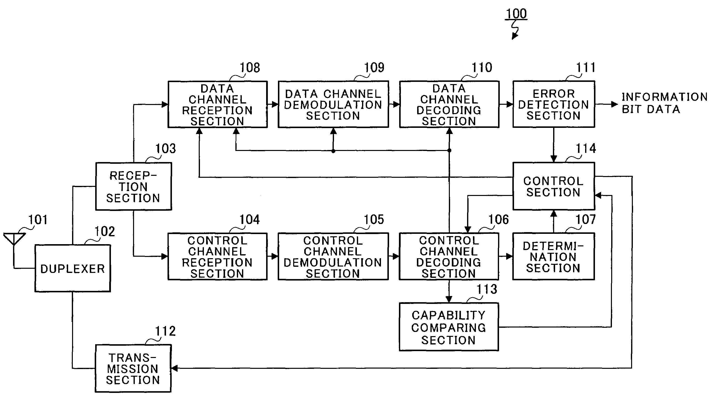
[0019]FIG. 3 is a block diagram illustrating a configuration of a reception apparatus according to one embodiment of the present invention. In FIG. 3, reception apparatus 100 according to this embodiment has capability comparing section 113. When determination section 107 determines there is a control channel intended for reception apparatus 100, the section 113 compares control information transmitted on the control channel with the reception capability of reception apparatus 100 to check reliability of the determination about the control channel that is determined to be for reception apparatus 100. Reception apparatus 100 further has control section 114. The section 114 does not receive a data channel nor perform transmission of an ACK signal and NACK signal unless the control information is within a scope of the reception capability of reception apparatus 100 ...


PUM


Abstract

When a determination section of a reception apparatus determines that a control channel is intended for the reception apparatus, a comparing section of the reception apparatus compares control information transmitted on the control channel with a reception capability of the reception apparatus. A data channel reception section of the reception apparatus receives a data channel when the control information is within the reception capability of the reception apparatus, but does not receive the data channel when the control information exceeds the reception capability of the reception apparatus. When the control information exceeds the reception capability of the reception apparatus, the transmission section does not transmit an ACK signal and a NACK signal with respect to the data channel.

Description

TECHNICAL FIELD[0001]The present invention relates to a reception apparatus and reception method using control information transmitted on a control channel in decoding information data transmitted on a data channel.BACKGROUND ART[0002]FIG. 1 is a diagram illustrating control channels transmitted from a transmission apparatus. In the figure, the control channels are used in transmitting information necessary for performing reception, demodulation and decoding on a data channel i.e. control information including the number of multicodes, modulation scheme, the number of information bits, and so on. When there are a plurality of reception apparatuses, information indicating which reception apparatus the channel is for is coded and transmitted on each control channel, so that each reception apparatus is able to detect the control channel for the reception apparatus from among multiple received control channels.[0003]FIG. 2 is a block diagram illustrating a configuration of a conventiona...

Claims


Application Information

Patent Timeline
Patent Type & Authority Patents(United States)
IPC IPC(8): G08C25/02G01R31/28H04B1/00H04B1/16H04L1/16H04B1/707H04B1/7103H04B7/26H04L1/00H04L1/18H04L29/02H04W4/00H04W4/18H04W8/22H04W28/00H04W28/04H04W28/06H04W28/18
CPCH04L1/0083H04L1/1812H04L1/1854H04W28/06H04W8/22H04W28/04H04L1/1829H04W88/02H04W48/12
Inventor HIRAKI, TOSHIAKISUZUKI, HIDETOSHI
Owner PANASONIC CORP
Why Eureka
Try Eureka