Magnetic disk drive to alleviate damage from thermal asperity

a technology of thermal asperity and magnetic disk, which is applied in the field of magnetic disk drives, can solve the problems of head damage, head head contact and the head damage cannot be prevented or alleviated. , to achieve the effect of preventing or alleviating the damage to the head

Inactive Publication Date: 2007-08-07
HITACHI GLOBAL STORAGE TECH NETHERLANDS BV
View PDF4 Cites 5 Cited by
  • Summary
  • Abstract
  • Description
  • Claims
  • Application Information

AI Technical Summary

Benefits of technology

[0008]The method described in Patent Document 1 is used to prevent the defective sections on the magnetic disk from growing / expanding by, for example, contact with the head and thus making it impossible to read the information existing in the defective sections and in adjacent regions. This method is therefore intended mainly to protect the data on the magnetic disk.
[0012]A feature of the present invention is to prevent or alleviate damage to the MR head of a magnetic disk, caused by the passage of the MR head over the TA-causing sections on the magnetic disk.
[0019]The present invention makes it possible to prevent or alleviate damage to MR heads.

Problems solved by technology

Such damage to the element- section of the head may cause problems with the head.
In a magnetic disk drive with a plurality of heads, when data within the same cylinder is read / written between other heads and disks, MR heads associated with the tracks where TA-causing sections are present move past the TA-causing sections and damage the element sections of the heads.
Also, since only the cylinders to which the defective tracks that have become defective sections belong are registered, if the defect is a projection, contact between the head and the projection cannot be prevented or alleviated.
For these reasons, head damage due to the presence of the TA-causing sections (projections) on disks cannot be prevented using conventional defect-registering methods.

Method used


Image

  • Magnetic disk drive to alleviate damage from thermal asperity
  • Magnetic disk drive to alleviate damage from thermal asperity
  • Magnetic disk drive to alleviate damage from thermal asperity

Examples


Embodiment Construction

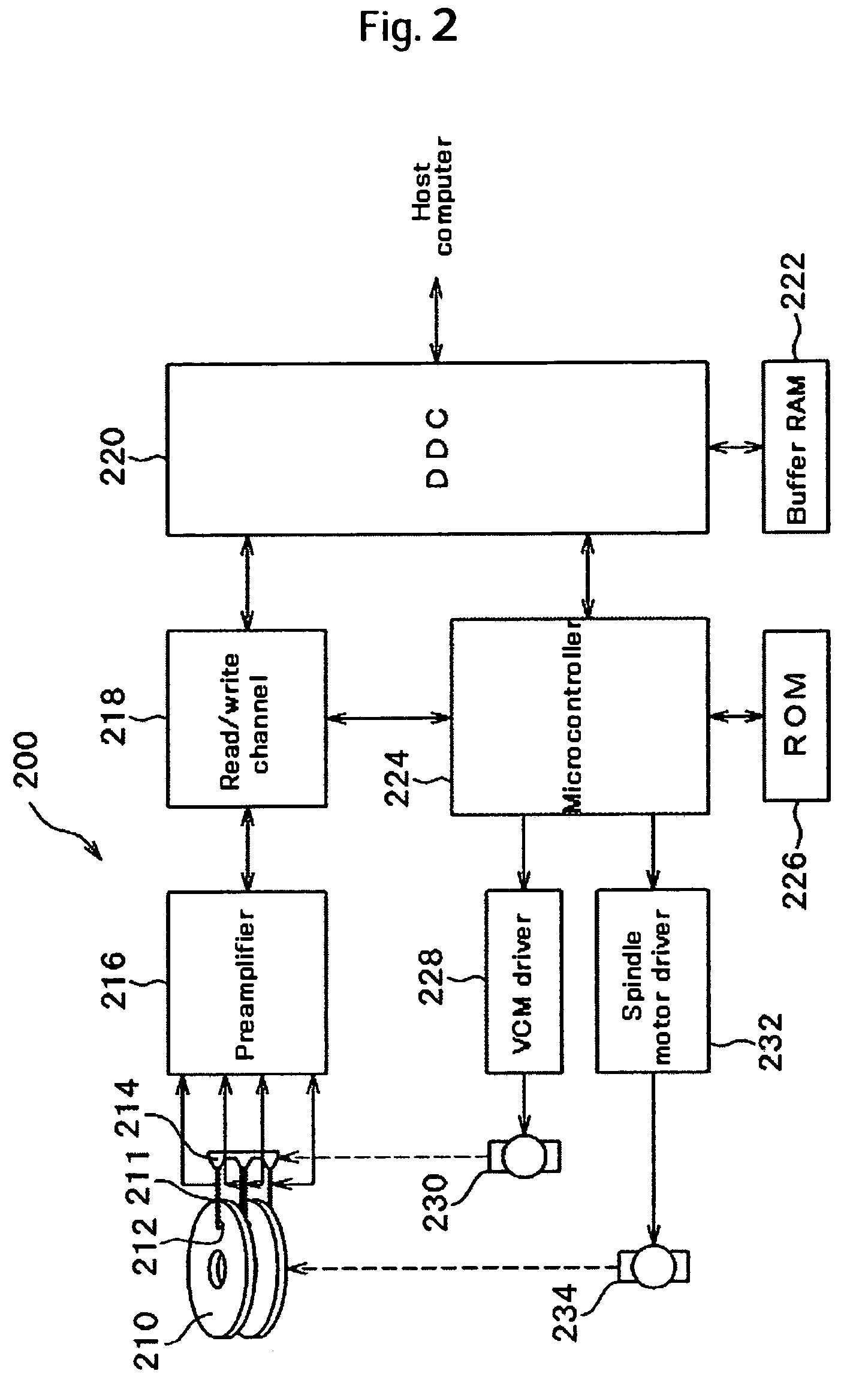
[0026]FIG. 2 is a configuration diagram of a magnetic disk drive 200 according to an embodiment of the present invention. Disks 210 are each rotated by a spindle motor 234, and one MR head 212 is disposed on one associated surface of each disk 210. Each MR head 212 is installed on an associated head arm 211 that extends from a carriage 214 to the disk 210. The carriage 214 has a voice coil motor (VCM) 230 for driving the head arm 211, thus changing a position of the MR head 212, and reading data from specific positions on one or more of the disks 210 or writing data into these specific positions.

[0027]A preamplifier 216 amplifies a signal that has been picked up by the MR head 212, and supplies the signal to a read / write channel 218. During write operations, the preamplifier 216 receives encoded write data signals from the read / write channel 218 and sends the signals to the MR head 212. During read operations, the read / write channel 218 detects data pulses from the reading signal su...


PUM

PropertyMeasurementUnit
constant speedaaaaaaaaaa
magnetoresistiveaaaaaaaaaa
widthaaaaaaaaaa

Abstract

Embodiments of the invention prevent or alleviate head damage ascribable to the TA-causing sections (projections) of disks (TA is thermal asperity). With respect to a TA-causing section that has been detected during initial defect registration, X±A tracks in a radial direction and Y±B sectors (or Y±B bytes of space) in a circumferential direction, with the TA-causing section as a center, are registered collectively during primary registration. Following this, secondary registration is conducted to register a region ranging from±several tens of tracks to several hundreds of tracks present in a radial direction, and all sectors (or all bytes of space) present in a circumferential direction, with a track of the detected TA-causing section as a center. Furthermore, a cylinder of a region equivalent to the same radial positions as those of the secondary registration is registered (as tertiary registration) for all disks, except for the disk where the TA-causing section was detected. If an available data storage capacity of the magnetic disk drive reaches or exceeds a certain rate with respect to an overall capacity of the drive, the tertiary registration and the secondary registration are released and removed from registered TA sections.

Description

CROSS-REFERENCES TO RELATED APPLICATIONS[0001]This application claims priority from Japanese Patent Application No. JP2005-052472, filed Feb. 28, 2005, the entire disclosure of which is incorporated herein by reference.BACKGROUND OF THE INVENTION[0002]The present invention relates to a magnetic disk drive including a magnetic disk medium that is rotationally driven and a magnetoresistive (MR) head that writes information onto or reads written information from magnetic disk media. More particularly, the invention is concerned with a magnetic disk drive that includes a function for preventing or alleviating trouble with the element section of an MR head due to the occurrence of thermal asperity on a magnetic disk.[0003]The surface of a magnetic disk (hereinafter, may also be referred to simply as the disk) which is a recording medium of a magnetic disk drive is formed of a number of very thin layers stacked on one another from the disk substrate side in order, such as an underlayer, a...

Claims


Application Information

Patent Timeline
Patent Type & Authority Patents(United States)
IPC IPC(8): G11B21/02
CPCG11B19/04G11B20/10203G11B27/329G11B2005/001G11B2220/2525
Inventor YORI, TAKEO
Owner HITACHI GLOBAL STORAGE TECH NETHERLANDS BV
Why Eureka
Try Eureka