Recording reproducing apparatus and recording reproducing method

a recording reproducing and recording technology, applied in the direction of digital signal error detection/correction, recording signal processing, instruments, etc., can solve the problems of recording processing itself failing, generating a defective part on the medium, and unable to read out data, etc., to achieve the effect of suppressing the transfer ra

Inactive Publication Date: 2013-12-31
HITACHI-LG DATA STORAGE +1
View PDF9 Cites 2 Cited by
  • Summary
  • Abstract
  • Description
  • Claims
  • Application Information

AI Technical Summary

Benefits of technology

[0005]At the present time, there are recording reproducing apparatus which conducts data recording by irradiating laser light from a semiconductor laser to an optical disc-shaped recording medium represented by a CD-R / RW (CD Recordable / Rewritable), DVD±R / RW (DVD±Recordable / Rewritable Disc), DVD-RAM (DVD-Re-writable), and Blu-ray Disc (hereafter referred to as BD). In the rewritable or write once optical disc medium, a defective part is generated on the medium by a scratch resulting from partial damage of the medium, a fingerprint, dirt, degradation of a recording film, or the like. Even if recording is conducted on the defective part, the possibility that it will become impossible to read out data becomes high. As one method for avoiding such a defect of the disc face and prolonging the disc life, there is a defect management method. This method is applied to the DVD-RAM and this fact is described in pp. 29˜31 in “DVD-RAM technique” edited by Triceps Planning Department and published by Triceps, 2000. This technique is applied to the BD as well, and a cluster recording of which has failed during recording to a user data area with a cluster taken as the unit, or a cluster recoding of which has been successful but judged in the verification of the cluster to be irreproducible is recorded to a replacement area provided in the disc. In addition, the cluster corresponds to a minimum recording block unit in the present invention. And address information for the detected defective cluster and address information of the cluster recorded in the replacement area are registered in a management area provided in the disc as a defect list (DFL). At the time of reproducing, it becomes possible to maintain the interchangeability by reading the DFL beforehand and reading out the cluster corresponding to the address in which the replacement recording has been conducted, instead of reading a cluster corresponding to a cluster address for which a recording instruction has been issued by a higher rank device, as it is.
[0009]Therefore, an object of the present invention is to suppress the lowering of the recording transfer rate by paying attention to the registering method of defective blocks.
[0011]According to the present invention, it is possible to hold down the number of times of recording processing accompanied by seek processing in the RAW processing and implement the suppression of the transfer rate lowering.

Problems solved by technology

In the rewritable or write once optical disc medium, a defective part is generated on the medium by a scratch resulting from partial damage of the medium, a fingerprint, dirt, degradation of a recording film, or the like.
Even if recording is conducted on the defective part, the possibility that it will become impossible to read out data becomes high.
A first case is a case where recording processing itself has failed.
If recording of a first block which is the unit of RAW fails, a shift to recording processing of the next second block is conducted, however, it is supposed that the recording of the second block fails in the same way and recording fails up to the final block in the RAW processing in the same way.
It takes a considerable time as compared with the case where recording processing is conducted contiguously without being accompanied by seek processing.
This results in a problem of a lowered recording transfer rate.

Method used


Image

  • Recording reproducing apparatus and recording reproducing method
  • Recording reproducing apparatus and recording reproducing method
  • Recording reproducing apparatus and recording reproducing method

Examples


first embodiment

[0019]Hereafter, an embodiment of the present invention will be described with reference to the drawings.

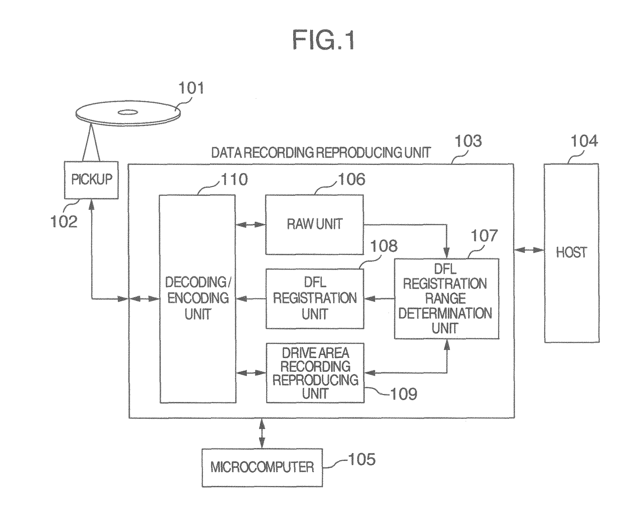
[0020]FIG. 1 is a block diagram representing a configuration of a recording reproducing apparatus according to the embodiment of the present invention. The configuration will be described with reference to FIG. 1.

[0021]In FIG. 1, a reference numeral 101 denotes an optical disc on which data can be recorded and reproduced. The optical disc 101 has a user data recording area, a disc management information recording area, a replacement processing data recording area, and a drive area for the recording reproducing apparatus to freely record and reproduce. A reference numeral 102 denotes a pickup for reading a recorded signal from the optical disc 101. A reference numeral 103 denotes a data recording reproducing unit. Although not illustrated, the data recording reproducing unit 103 includes all units required to output data read out from the pickup 102 to a host 104 which is an exter...


PUM

PropertyMeasurementUnit
areaaaaaaaaaaa
defectaaaaaaaaaa
timeaaaaaaaaaa

Abstract

If a recording error has occurred during RAW, then subsequent recording reproducing processing is omitted in a predetermined range, and all blocks omitted in the processing are handled as defective blocks, DFL-registered, and recorded in a replacement area. As a result, it becomes possible to hold down the number of times of recording processing accompanied by seek processing in the RAW processing, and transfer rate lowering can be solved.

Description

INCORPORATION BY REFERENCE[0001]The present application claims priority from Japanese application JP 2011-047103 filed on Mar. 4, 2011, the content of which is hereby incorporated by reference into this application.BACKGROUND OF THE INVENTION[0002]The present invention relates to a recording reproducing apparatus and a recording reproducing method. In particular, the present invention relates to a registration method of a defect list (DFL) in an apparatus which conducts recording and reproducing by using a replacement processing data recording area in a medium.[0003]As for a background technique in the present technical field, there is a defect management method called linear replacement, as one of methods for avoiding defects on a disc face and prolonging the disc life. According to the linear replacement, data is not recorded on the defective part, but data is recorded in a replacement area (alternative recording area) provided on the same optical disc. The linear replacement is d...

Claims


Application Information

Patent Timeline
Patent Type & Authority Patents(United States)
IPC IPC(8): G11B5/09
CPCG11B20/1889G11B2220/2537G11B2020/1893G11B20/1879G11B2020/1826
Inventor AKAHOSHI, KENJI
Owner HITACHI-LG DATA STORAGE
Why Eureka
Try Eureka