Electromagnetic lens antenna device for bistatic radar

a technology of electromagnetic lens and antenna device, which is applied in the direction of antennas, instruments, climate sustainability, etc., can solve the problems of affecting the observation affecting the performance of the radar apparatus, so as to reduce the weight, prolong the life, and save the cos

Inactive Publication Date: 2010-02-04
SUMITOMO ELECTRIC IND LTD
View PDF5 Cites 236 Cited by
  • Summary
  • Abstract
  • Description
  • Claims
  • Application Information

AI Technical Summary

Benefits of technology

[0010]Accordingly, it is an objective of the present invention to provide a bistatic electromagnetic lens antenna device that is capable of performing volume scanning with an inexpensive and simple configuration and has a reduced weight and an extended life.

Problems solved by technology

However, in a monostatic radar apparatus, approximately one hundredth (−20 dB) of the transmission power from the transmitter leaks to the receiver.
This significantly degrades the observation performance of the radar apparatus and damages the receiver.
This increases the size of the radar apparatus and the costs.
Also, since the duty ratio (transmission period / cycle of pulse repetition) of the high-frequency pulsed signals is several percent, the observation performance of the radar apparatus is significantly degraded.
A great load is thus applied to the antenna drive mechanism.
The antenna device is thus likely to be damaged.
This shortens the life of the apparatus.
This also increases the size and costs of the antenna device.

Method used


Image

  • Electromagnetic lens antenna device for bistatic radar
  • Electromagnetic lens antenna device for bistatic radar
  • Electromagnetic lens antenna device for bistatic radar

Examples


Embodiment Construction

[0025]One embodiment of the present invention will now be described with reference to FIGS. 1 to 4.

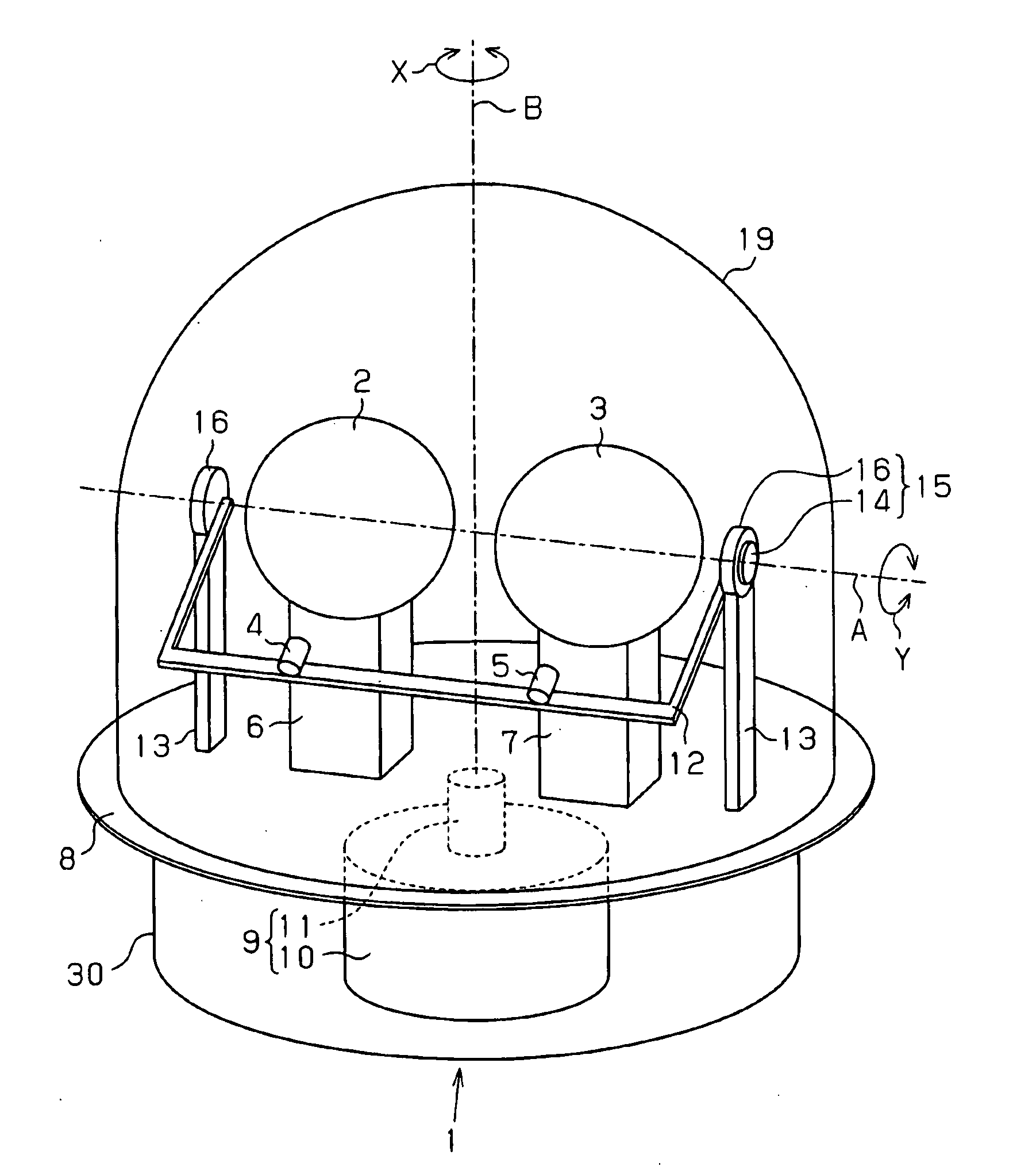
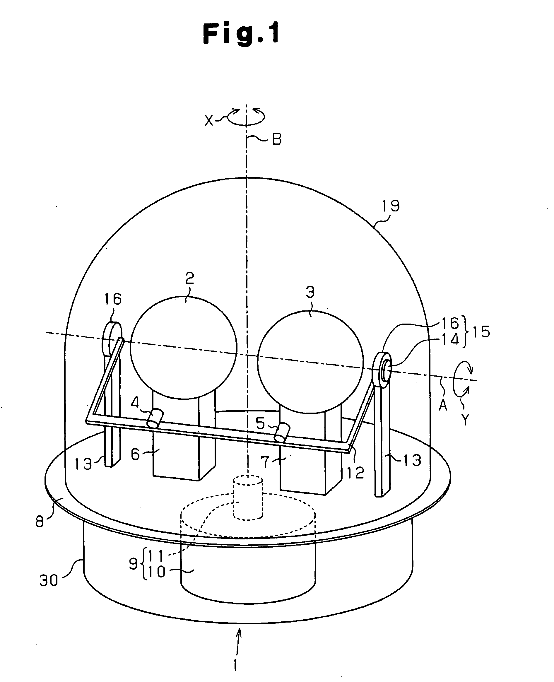
[0026]As shown in FIG. 1, an electromagnetic lens antenna device 1 includes an electromagnetic lens 2 for transmission, an electromagnetic lens 3 for reception, a primary radiator 4 located at the focal point of the electromagnetic lens 2, and a primary radiator 5 located at the focal point of the electromagnetic lens 3.

[0027]The electromagnetic lenses 2, 3 are spherical Luneberg lenses. A Luneberg lens is formed of dielectric material and includes a spherical core located at the center, and a plurality of spherical shells of different diameters covering the core. The dielectric material refers to a material that displays paraelectricity, ferroelectricity, or antiferroelectricity, and has no electric conducting property. The relative permittivity of the electromagnetic lenses 2, 3 changes at a constant rate along a radial direction. In each of the electromagnetic lenses 2, 3, the relat...


PUM


Abstract

An electromagnetic lens device includes an electromagnetic lens for transmission, an electromagnetic lens for reception, two primary radiators each located at a focal point of one of the electromagnetic lenses, an arm holding the primary radiators, and a table. The arm is rotatable about a first axis that extends through the centers of the electromagnetic lenses. The table is rotatable about a second axis that is perpendicular to the first axis. The primary radiators rotate about the first axis together with the arm, and rotate about the second axis together with the table.

Description

FIELD OF THE INVENTION[0001]The present invention relates to an electromagnetic lens antenna device that uses electromagnetic lenses for emitting and receiving radio waves.BACKGROUND OF THE INVENTION[0002]Various type of radar apparatuses are generally used for weather observation and air control. Such a radar apparatus emits high-frequency radio waves such as microwaves toward a target from an antenna, and receives reflected waves to detect the size, shape, distance, and speed of the target. For example, a weather radar apparatus emits radio waves to water droplets in the atmosphere and detects the size of a precipitation area and the precipitation amount by analyzing received reflected waves.[0003]Such radar apparatuses include the monostatic type and the bistatic type. A monostatic radar apparatus emits and receives signals using a single antenna. That is, a monostatic radar apparatus alternately connects the antenna to a transmitter and a receiver. A bistatic radar apparatus has...

Claims


Application Information

Patent Timeline
Patent Type & Authority Applications(United States)
IPC IPC(8): H01Q15/08
CPCG01S7/03G01S7/038G01S13/951H01Q1/42H01Q25/008H01Q3/14H01Q15/02H01Q19/06H01Q3/04Y02A90/10
Inventor IMAI, KATSUYUKI
Owner SUMITOMO ELECTRIC IND LTD
Why Eureka
Try Eureka