Sheet conveying apparatus and image forming apparatus

a technology of conveying apparatus and sheet, which is applied in the direction of transportation and packaging, electrographic process, instruments, etc., can solve the problems of sheet damage, jam, and variation of the conventional switching operation of the switching member, and achieve the effect of simple and inexpensive configuration

Active Publication Date: 2015-03-31
CANON KK
View PDF23 Cites 13 Cited by
  • Summary
  • Abstract
  • Description
  • Claims
  • Application Information

AI Technical Summary

Benefits of technology

[0014]The invention has been made to solve the above-described problems. The invention is desirable to provide an apparatus that conveys a sheet with a simple and inexpensive configuration to cope with a case in which an interval between sheets to be conveyed continuously is short.

Problems solved by technology

Meanwhile, the conventional switching operation of the switching member has a certain amount of variation due to a response delay of the solenoid.
In the worst case, the leading end of the succeeding sheet reaches the switching member before the switching operation of the switching member is completed, and thus a jam may occur or the sheet may be damaged.
However, as the conveying force increases, a size of a motor becomes larger, resulting in increasing the cost.
In addition, due to high image quality in recent years, when the sheet is interposed with the switching member and the guide at a state in which the sheet temperature immediately after fixing is high and a fixed image surface and a conveying rib come in contact with each other, there is a conspicuous problem in that unevenness density of the image between a contact surface and a non-contact surface with the conveying rib is caused.

Method used


Image

  • Sheet conveying apparatus and image forming apparatus
  • Sheet conveying apparatus and image forming apparatus
  • Sheet conveying apparatus and image forming apparatus

Examples


first embodiment

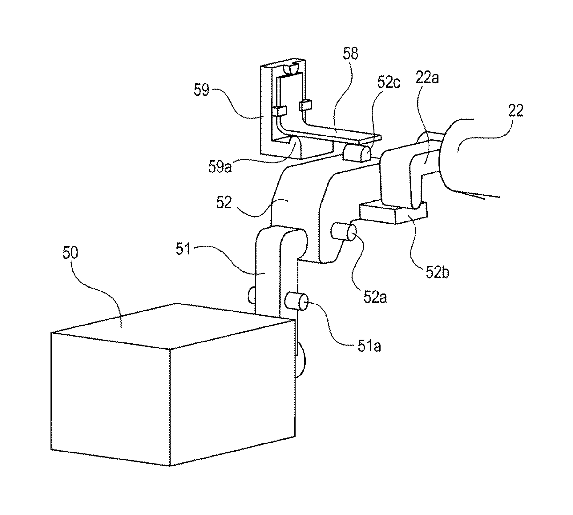
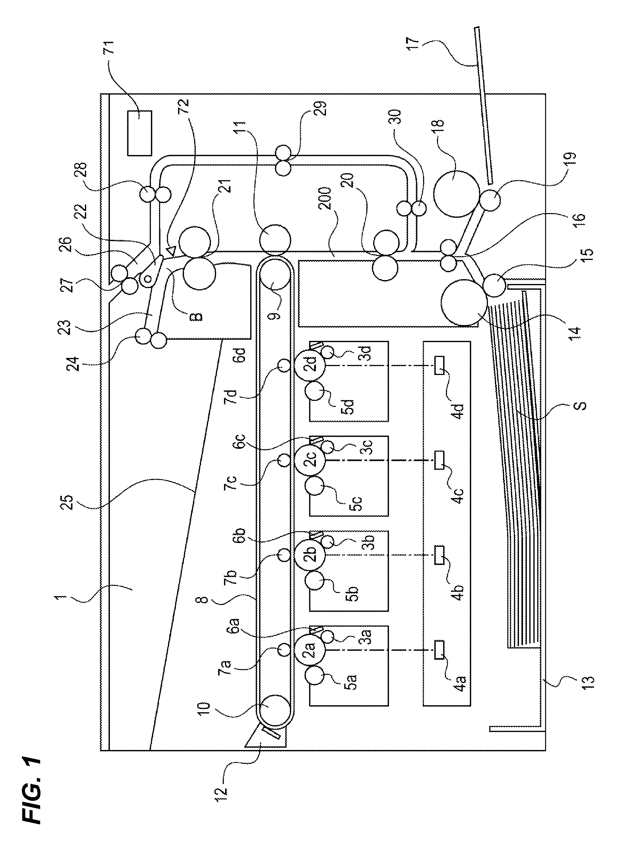
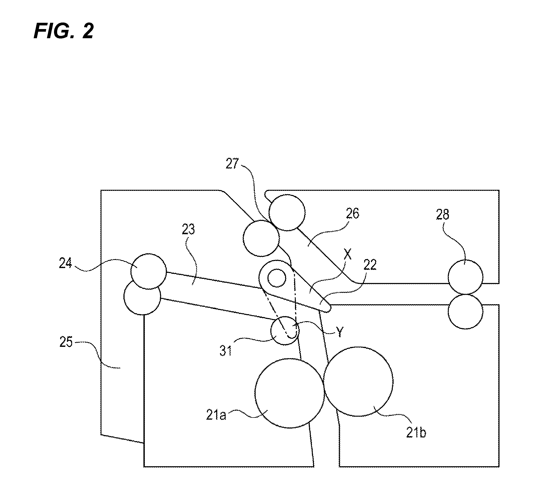
[0034][First Embodiment]FIG. 1 is an example of a sheet conveying apparatus according to the invention and a cross-sectional view illustrating a configuration of an image forming apparatus of a color electrophotographic system, and FIG. 2 is a cross-sectional view illustrating a detailed configuration of a periphery a double-side switching member, which is a conveying path switching member.

[0035](Overall Configuration of Image Forming Apparatus) An image forming apparatus 1 is provided with four drum-shaped image bearing members which are juxtaposedly arranged in a substantially horizontal direction as an image bearing member, that is, photosensitive drums 2 (2a, 2b, 2c, and 2d). The photosensitive drum 2 is rotationally driven in a clockwise direction in FIG. 1.

[0036]In addition, a charging device 3 (3a, 3b, 3c, and 3d) is provided to uniformly charge a surface of the photosensitive drum 2. Moreover, a scanner unit 4 (4a, 4b, 4c, and 4d) is provided to form an electrostatic latent ...

second embodiment

[0098][Second Embodiment] Another embodiment of the invention will be described below with reference to FIGS. 9 to 11. A configuration of an image forming apparatus in the second embodiment is the same as that in the first embodiment, and the same or similar components as those in the first embodiment are denoted by the same reference numerals and the repeated description will not be presented. Hereinafter, parts different from the first embodiment will be mainly described.

[0099]FIG. 9 is a diagram illustrating a detailed switching configuration of the double-side switching member 22 of the image forming apparatus 1 according to the second embodiment. A switching member return compression spring 60 is an unequal pitch spring, and a pitch is different in the middle of spring. A compression spring holding portion 61 is provided in a part of the sheet guide portion of the reverse conveying path 26 (FIGS. 7A to 7C) to hold the switching member return compression spring 60.

[0100]Arrows i...

third embodiment

[0112][Third Embodiment] Next, further another embodiment of the invention will be described with reference to FIGS. 13 to 16. A configuration of an image forming apparatus in a third embodiment is the same as that in the first embodiment, and the same or similar components as those in the first embodiment are denoted by the same reference numerals and the repeated description will not be presented. Hereinafter, parts different from the first embodiment will be mainly described.

[0113]FIG. 13 is a diagram illustrating a detailed switching configuration of the double-side switching member 22 according to a third embodiment.

[0114]A switching member abutting portion 62a of a cam-attached connection plate 62 abuts on the arm portion 22a of the double-side switching member 22. A cam 63 (cam-shaped member) is pressed against the cam-attached connection plate 62 side by a cam pressure spring 64. In addition, the cam pressure spring 64 is held by a pressure spring holding portion 65. Further...


PUM

PropertyMeasurementUnit
driving forceaaaaaaaaaa
forceaaaaaaaaaa

Abstract

Provided is a sheet conveying apparatus which conveys a sheet, includes: a sheet conveying path which diverges into a first conveying path and a second conveying path at a diverging point; a guide member which is movable between a first position where the guide member guides the sheet to the first conveying path and a second position where the guide member guides the sheet to the second conveying path; a driving portion which is configured to move the guide member to the second position from the first position; and a holding portion which, in a case that the guide member is driven by the driving portion to move to the second position from the first position, provides a load to the driving by the driving portion and holds the guide member at a third position between the first position and the second position.

Description

BACKGROUND OF THE INVENTION[0001]1. Field of the Invention[0002]The invention relates to a sheet conveying apparatus which conveys a sheet within a sheet conveying path.[0003]2. Description of the Related Art[0004]In the related art, an image forming apparatus of an electrophotographic system, such as a printer, a copying machine, or a facsimile is configured so as to form an image on double sides of a sheet by forming the image one side of the sheet with an image forming portion, reversing the sheet with a reverse portion, and conveying once again the reversed sheet to the image forming portion.[0005]In such an apparatus, a switching member, in which a flapper-shaped member is swingingly configured, is provided to make a switching such that the sheet is conveyed to a discharge conveying path, which discharges the sheet into the outside of the apparatus, or a reverse conveying path, which is provided with the reverse portion. A solenoid is used as a switching unit which switches the...

Claims


Application Information

Patent Timeline
Patent Type & Authority Patents(United States)
IPC IPC(8): B65H39/10B65H29/58B65H29/60B65H85/00G03G15/00G03G15/23
CPCB65H29/58B65H29/60B65H85/00G03G15/234G03G15/6529B65H2404/6112B65H2404/63B65H2404/741B65H2404/7414B65H2301/33312B65H2404/632B65H2555/13B65H2801/06G03G2215/00675
Inventor SUZUKI, MASATO
Owner CANON KK
Why Eureka
Try Eureka