Multi-wavelength generating method and apparatus based on flattening of optical spectrum

a multi-wavelength and optical spectrum technology, applied in multiplex communication, instruments, optical elements, etc., can solve the problems of inability to dynamically control the deviation of power level among longitudinal modes, incoherent and thus unsuitable for dense wdm transmissions involving a large number of wavelengths, and ineffective design and production

Inactive Publication Date: 2004-05-27
NIPPON TELEGRAPH & TELEPHONE CORP
View PDF4 Cites 14 Cited by
  • Summary
  • Abstract
  • Description
  • Claims
  • Application Information

AI Technical Summary

Benefits of technology

[0012] It is a second object of the present invention to provide a collective multi-wavelength generating apparatus which has a simple and inexpensive configuration and which makes it possible to generate, without the need to design a complicated optical circuit, a WDM signal with a flattened optical spectrum by modulating a light with a single central frequency by means of an electric signal of a particular pulse repetition frequency.
[0014] It is a fourth object of the present invention to provide a multi-wavelength light source having a simple and inexpensive configuration that does not require a complicated optical circuit to be designed, the light source being realized by taking a plurality of lights into the above described multi-wavelength generating apparatus and making it possible to generate a WDM-signal with a flattened optical spectrum without any interfering noise.
[0015] A method according to the present invention comprises a first process of obtaining a discrete spectrum of a mode spacing .DELTA.f using an output light obtained by modulating the amplitude or phase of a CW output from a single-wavelength light source or an output light from a pulsed light source or an optical-pulse output circuit for outputting a pulsed light of a repetition frequency .DELTA.f, and a second process of modulating the discrete spectrum of the mode spacing .DELTA.f at a frequency .OMEGA.<2fm when the discrete spectrum has a band 2fm, thereby making it possible to dynamically control power level deviations among the longitudinal modes of the discrete spectrum.

Problems solved by technology

A light obtained by slicing a spectrum of the ASE light, however, is incoherent and thus unsuitable for dense WDM transmissions involving a large number of wavelengths.
Such design and production, however, is in effect difficult.
Further, since the shape of the optical spectrum is uniquely determined by its design parameters, it is impossible to dynamically control power level deviations among the longitudinal modes.
Moreover, the process of flattening an optical spectrum using the optical filter with the reverse transmission characteristic also has problems in design difficulty and uniquely decided output spectrum as in the above described supercontinuum generation.
Thus, when the pulse width t0 and the pulse repetition frequency .DELTA.f have a relationship t0 << (1 / .DELTA.f), since the current electric circuits have a modulating band of several tens of GHz, it is technically very difficult to execute the above second process.

Method used


Image

  • Multi-wavelength generating method and apparatus based on flattening of optical spectrum
  • Multi-wavelength generating method and apparatus based on flattening of optical spectrum
  • Multi-wavelength generating method and apparatus based on flattening of optical spectrum

Examples


eleventh embodiment

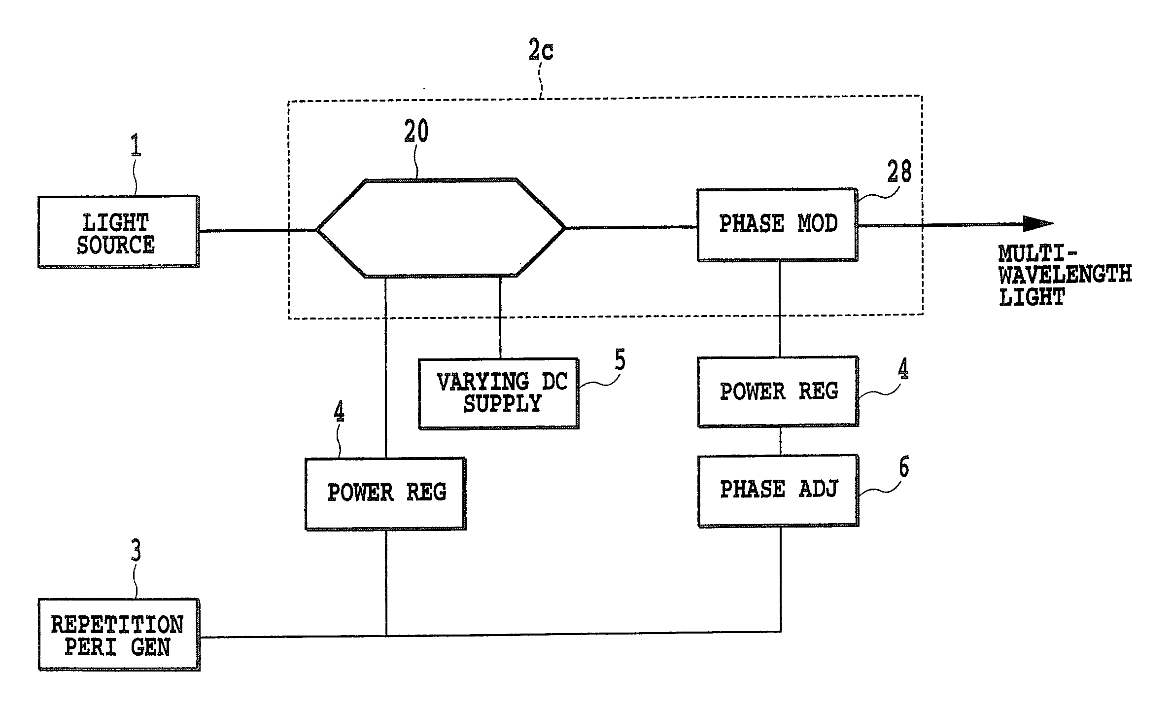
[0273] As described above, this embodiment provides the configuration comprising the modulating section having the at least one optical modulating means coupled together in series and arranged at the predetermined locations of the plurality of paths including the one to which the incident light of the single central wavelength is input, and the plurality of voltage applying means for independently regulating and applying the signal voltage of the predetermined period to the input port of the optical modulating means. In this configuration, a multi-wavelength light is generated by flattening the incident light depending on the regulated and applied signal voltage and the predetermined period of the signal voltage, thus making it possible to generate a WDM signal as a multi-wavelength light having a flattened optical spectrum, using the simple and inexpensive configuration and without the need to design a complicated optical circuit. [Application of the Multi-Wavelength Generating App...

second embodiment

[0281] (Second Embodiment of the Coherent Multi-Wavelength Signal Generating Apparatus)

[0282] FIG. 51 shows the second embodiment of the coherent multi-wavelength signal generating apparatus. The coherent multi-wavelength signal generating apparatus of this embodiment includes an optical amplifier 320 for amplifying a multi-wavelength light which amplifier is arranged between the multi-wavelength light source 311 and demultiplexer 312 of the configuration of the first embodiment so that part of the amplified multi-wavelength light is guided to the control circuit 350.

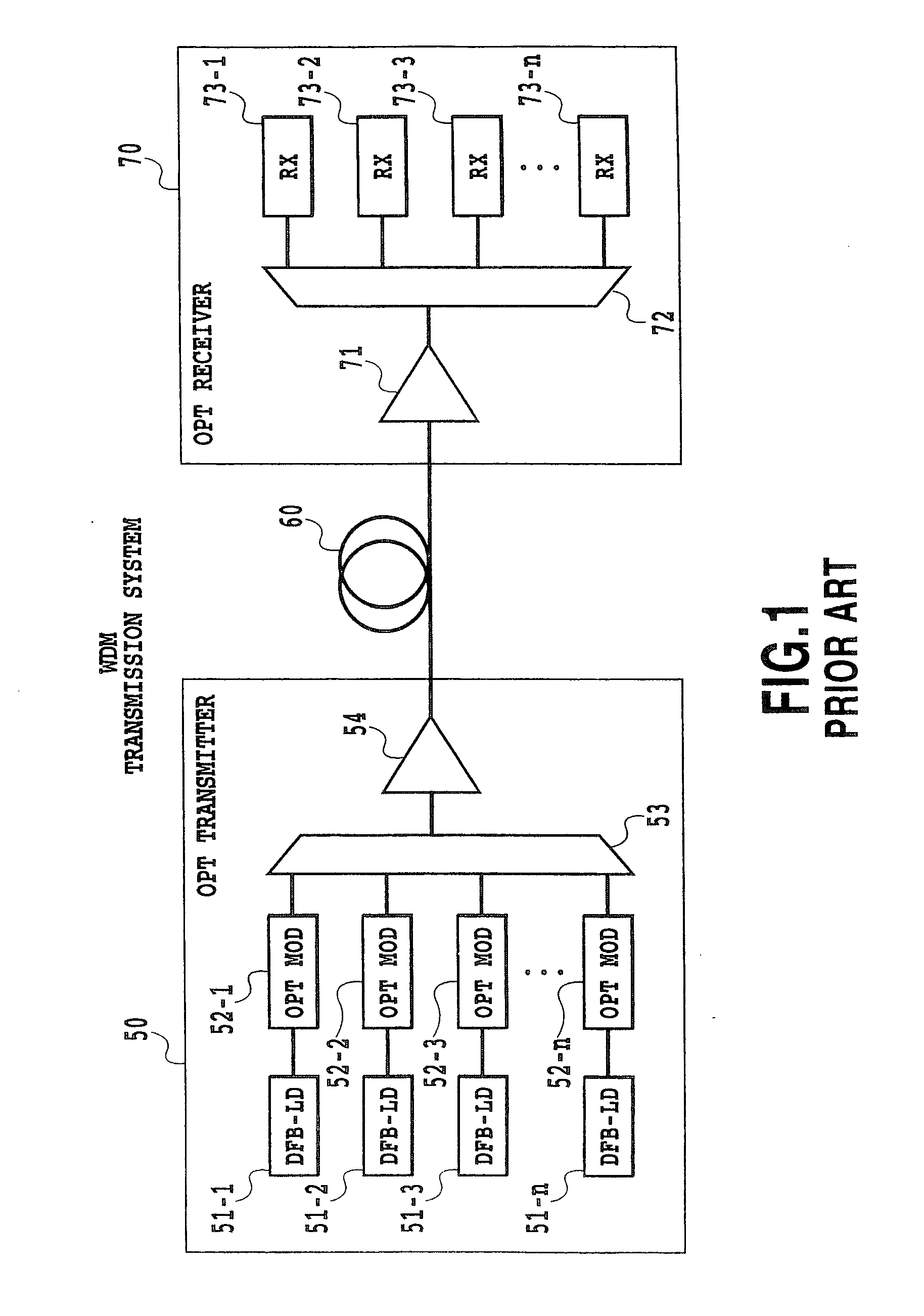
[0283] FIG. 52 is an example of the configuration of a WDM transmission system using the coherent multi-wavelength signal generating apparatus of the present invention. In FIG. 52, an optical receiving section 370 connected to a coherent multi-wavelength signal generating apparatus 10 via an optical amplifier 371 for amplifying a transmitted WDM (Wavelength Division Multiplexing) signal light, a demultiplexer 372 for de...

example 2

[0309] (Example 2 of Design of the Signal-to-Noise Ratio SNR for Outputs from the Modulator)

[0310] In the coherent multi-wavelength signal generating apparatus shown in FIG. 50 or 51, the band of a receiver 373 of the WDM transmission system shown in FIG. 52 is defined as Be[Hz], the demultiplexing band of the demultiplexer 372 is defined as B.sub.0[Hz], the signal mark rate is defined as M, the signal light intensity of an output from the i-th modulator is defined as P(i)[dBm], the intensity of the stimulated emission light in the output from this modulator is defined as Pc(i)[dBm], the intensity of the spontaneous emission light in the output from this modulator is defined as Ps(i)[dBm], an equivalent current flowing through the receiver is defined as Ieq[A], the rate of leakage from the j-th port to the i-th port of the multiplexer is defined as XT(j), the light intensity of a cross talk signal from the multiplexer is defined as Px(i)[dBm], shot noise in the signal components is ...


PUM

PropertyMeasurementUnit
widthaaaaaaaaaa
frequencyaaaaaaaaaa
repetition frequencyaaaaaaaaaa

Abstract

With respect to the relative intensity noise (RIN) for inputs to an optical modulator or the signal-to-noise ratio (SNR) for outputs therefrom, the optical modulator modulating coherent lights of different wavelengths obtained by slicing a spectrum of the multi-wavelength light, the shape of a spectrum of a multi-wavelength light is controlled so that predetermined RIN and SNR can be obtained in accordance with transmission system parameters (the type and distance of optical fibers, the number of repeaters), thus enabling design meeting a performance specification for a conventional transmission section using semiconductor lasers.

Description

[0001] This application is based on Japanese Patent Application Nos. 2000-207475 and 2000-207494 both filed Jul., 7, 2000, 2000-218424 filed Jul. 19, 2000 and 2000-266125 filed Sep. 1, 2000, the content of which is incorporated hereinto by reference.[0002] 1. Field of the Invention[0003] The present invention relates to a collective multi-wavelength generating technique for use in the field of optical communication technologies, and in particular, to elimination of power level deviations among the modes of a discrete optical spectrum, collective generation of a multi-wavelength light with a plurality of central wavelengths from a light with a single central wavelength, controlling an optical spectrum shape, while slicing a spectrum of coherent multi-wavelength output from a multi-wavelength light source and modulating the coherent multi-wavelength from the multi-wavelength light source with a plurality of optical modulators, output from the multi-wavelength light source so as to cau...

Claims


Application Information

Patent Timeline
Patent Type & Authority Applications(United States)
IPC IPC(8): G02F1/01H04B10/155H04B10/18H04J14/02
CPCG02F1/0121H04B10/505H04B10/5051H04B10/50572H04B10/50577H04J14/0221H04B10/50595H04B10/50597H04B10/506H04B10/508H04B10/564H04B10/50593
Inventor FUJIWARA, MASAMICHIARAYA, KATSUHIROTESHIMA, MITSUHIROKANI, JUNICHISUZUKI, KENICHI
Owner NIPPON TELEGRAPH & TELEPHONE CORP
Why Eureka
Try Eureka