Ink jet printing apparatus and method of controlling temperature of head of ink jet printing apparatus

a printing apparatus and ink jet technology, applied in printing, other printing apparatus, etc., can solve the problems of increasing affecting the efficiency of printing equipment, etc., to achieve uniform heating of the head, and reduce the cost of printing equipment.

Inactive Publication Date: 2005-10-25
CANON KK
View PDF14 Cites 12 Cited by
  • Summary
  • Abstract
  • Description
  • Claims
  • Application Information

AI Technical Summary

Benefits of technology

[0020]It is an object of the present invention to provide an ink jet printing apparatus with an inexpensive and simple configuration which sufficiently heats a head even in a low-temperature environment and which enables a proper image to be printed by stably ejecting ink.

Problems solved by technology

It is known that an ink jet printing apparatus or the like is subjected to various adverse effects of a variation in environmental temperature or in temperature of a head composed of integrated printing elements.
Moreover, with a higher grade of an image to be printed, the adverse effects of a variation in density or tone associated with the head temperature are more serious.
However, the above control is disadvantageous in that throughput decreases substantially owing to the heating time set for the head.
However, in this case, printing is executed with the printhead insufficiently heated.
Further, problems such as a nonuniform density are prone to occur.
Accordingly, this method is improper for high-grade image printing.
Furthermore, to heat the printhead during printing in order to avoid a decrease in throughput, a printing pulse and a heating pulse must be individually controlled, thereby requiring the apparatus to be complicated.
On the other hand, if the heating operation period is limited to the period in which no printing operation is performed, i.e. a sheet feeding period or a carriage acceleration or deceleration period, then insufficient heating may be provided during the heating operation period as with the case in which the upper limit on the heating time is set to a smaller value as described previously.
Further, during the heating operation period, motors for the transporting system and carriage are accelerated or decelerated to increase power consumption.
Thus, disadvantageously, if the printhead is to be further heated, the capacity of a power supply must be increased.
Further, it has been proposed that heat retention be executed depending on the type of printing by controlling heat retention when a noticeable high-grade image, which may create a problem as described above, is printed.
However, this increases costs and requires correction of a difference between the ink temperature and the environmental temperature caused by heat generated by the printing apparatus itself.
Therefore, the required control is complicated.

Method used


Image

  • Ink jet printing apparatus and method of controlling temperature of head of ink jet printing apparatus
  • Ink jet printing apparatus and method of controlling temperature of head of ink jet printing apparatus
  • Ink jet printing apparatus and method of controlling temperature of head of ink jet printing apparatus

Examples


first embodiment

[First Embodiment]

[0041]Embodiments of the present invention will be described below in detail with reference to the drawings.

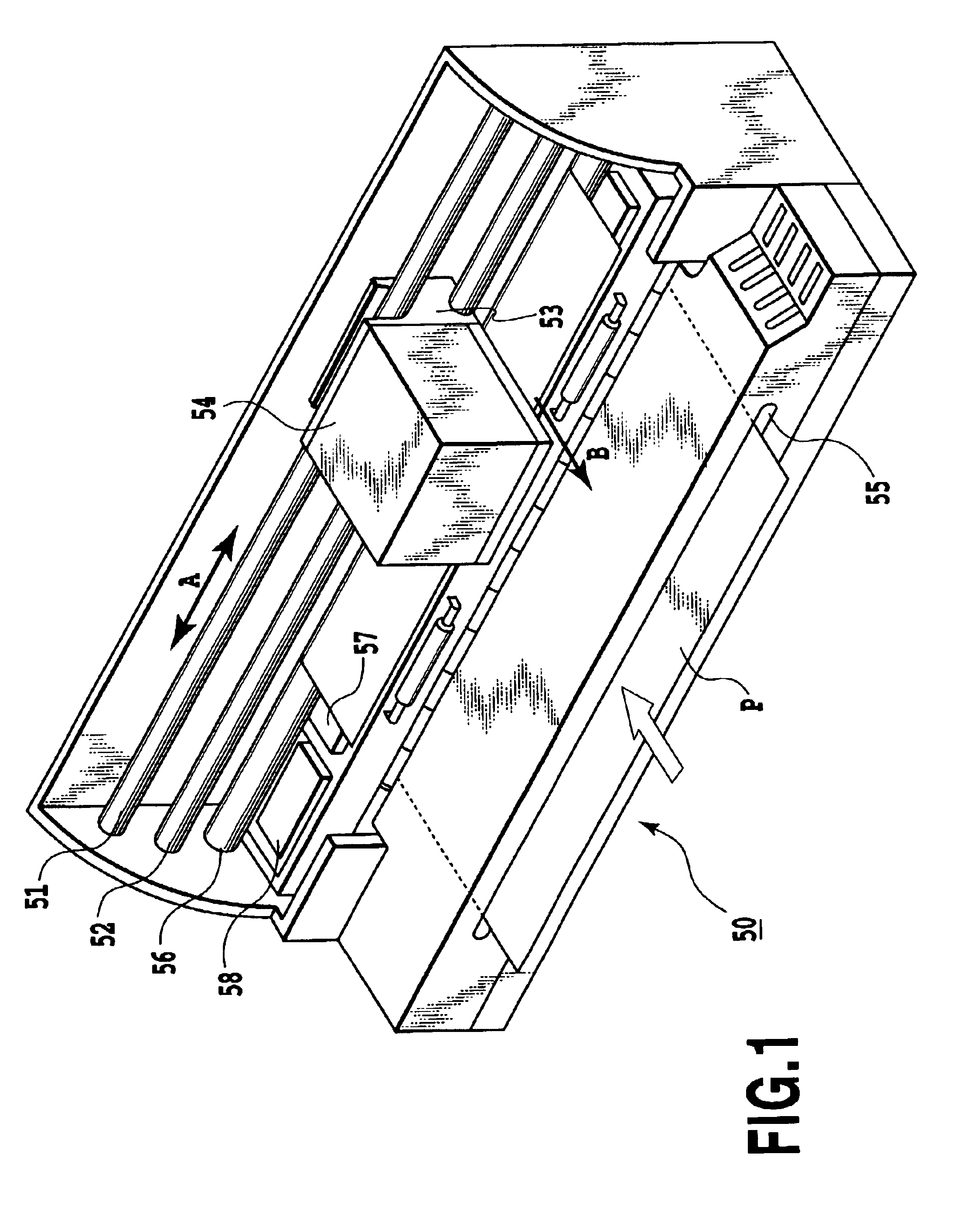
[0042]First, the configuration of an ink jet printing apparatus according to this embodiment will be described with reference to FIG. 1.

[0043]An ink jet printing apparatus 50, shown in FIG. 1, employs a serial scan method and has a carriage 53 supported along guide shafts 51 and 52 so as to reciprocate along a main-scanning direction, shown by arrow A. The carriage 53 is reciprocated in the main-scanning direction by a carriage motor and a driving force transmitting mechanism such as a belt which transmits driving force. The carriage 53 has a printhead 10 (not shown in FIG. 1) mounted thereon and an ink tank 54 also mounted thereon to supply ink to the print head 10. The printhead 10 and the ink tank 54 may constitute an ink jet cartridge.

[0044]Further, a printing medium P is inserted through an insertion port formed in a front surface of the apparatus and is...

second embodiment

[Second Embodiment]

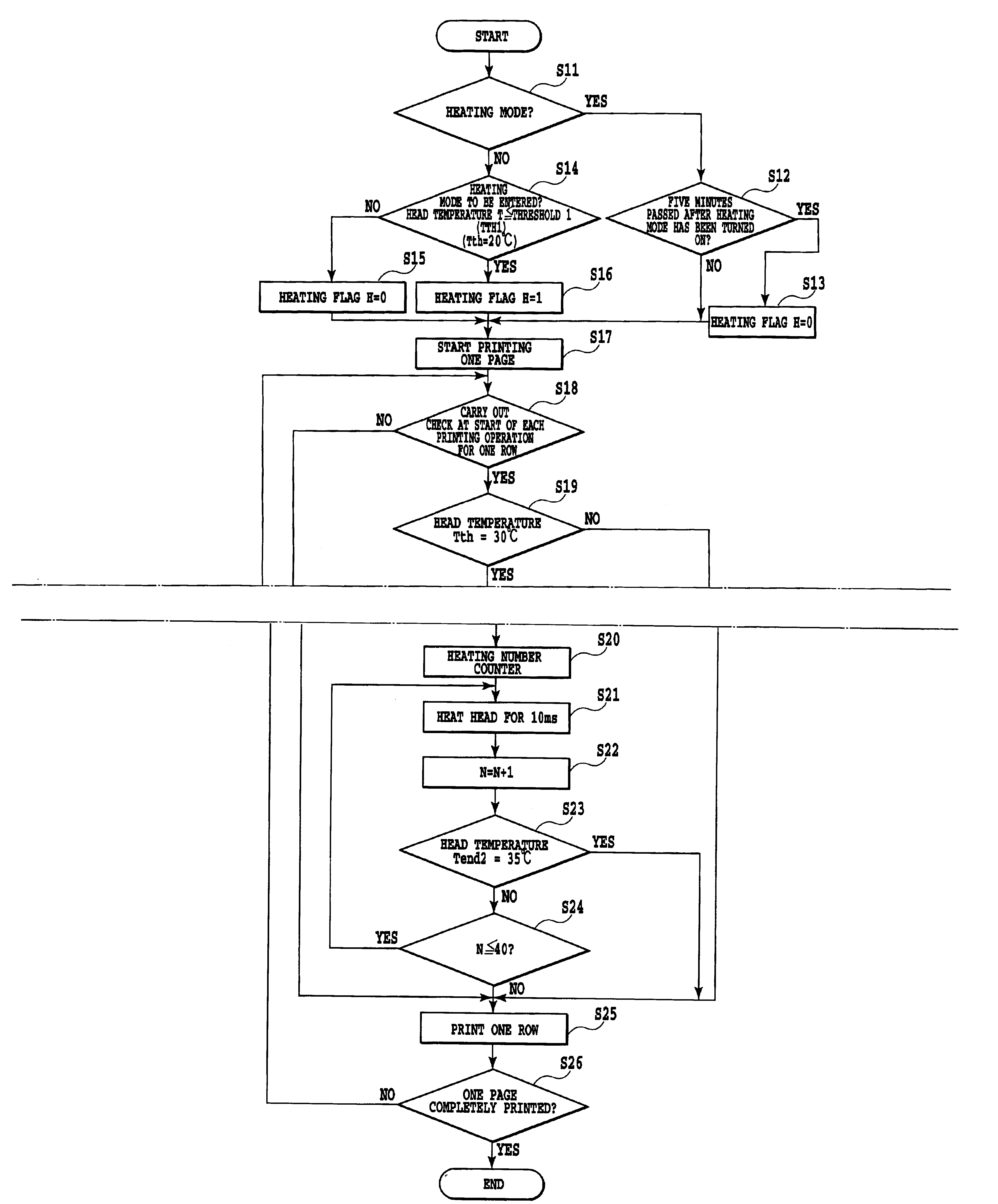
[0076]Next, a control operation performed according to a second embodiment will be described with reference to the flow chart in FIGS. 12A and 12B. The second embodiment also has the configuration shown in FIGS. 1 to 5.

[0077]When a print command is received, the heating flag H is first checked to determine whether or not the heating mode H has been set (step S21). If the heating mode H has not been set, the head temperature T is compared with the heating threshold temperature Tth1 (step S22). If the head temperature T is equal to or higher than the heating threshold temperature Tth1, the heating flag H is turned off (H=0). Then, a printing operation for one page is started without heating the printhead (step S26). Further, if it is determined that the head temperature T is lower than the heating threshold temperature Tth1, the heating flag H is turned on (H=1). Then, the target temperature Tend1, a heating time Theat1, and the number of repetitions L1 are set, and...


PUM


Abstract

The present invention relates to an ink jet printing apparatus which sufficiently heats a head even in a low-temperature environment, which enables a proper image to be printed by stably ejecting ink, and which can be inexpensively and simply constructed. According to the present invention, if the detected temperature of a printhead is lower than a first heating threshold temperature, a heating mode in which the printhead can be heated is set before a printing operation. Further, when the heating mode is set and the detected temperature of the printhead is lower than a second heating threshold temperature, a heating unit heats the printhead. Consequently, even in a low-temperature environment, the heating operation keeps ink in a desired condition suitable for printing.

Description

[0001]This application is based on Patent Application No. 2001-232916 filed Jul. 31, 2001 in Japan, the content of which is incorporated hereinto by reference.BACKGROUND OF THE INVENTION[0002]1. Field of the Invention[0003]The present invention relates to an ink jet printing apparatus that carries out printing using thermal energy and a method of controlling the temperature of a head of the ink jet printing apparatus, and in particular, to improvements in control of the head temperature in a low-temperature environment.[0004]2. Description of the Prior Art[0005]It is known that an ink jet printing apparatus or the like is subjected to various adverse effects of a variation in environmental temperature or in temperature of a head composed of integrated printing elements. This is because the temperature varies physical property values such as the viscosity or surface tension of ink. Further, with what is called a bubble jet (registered trade name) printing method of using thermal ener...

Claims


Application Information

Patent Timeline
Patent Type & Authority Patents(United States)
IPC IPC(8): B41J2/05B41J2/01
CPCB41J2/04528B41J2/04553B41J2/04563B41J2/0458
Inventor KAWATOKO, NORIHIROTAJIKA, HIROSHIFUJITA, MIYUKIKONNO, YUJIOGASAHARA, TAKAYUKIEDAMURA, TETSUYAMAEDA, TETSUHIROMASUYAMA, ATSUHIKO
Owner CANON KK
Why Eureka
Try Eureka