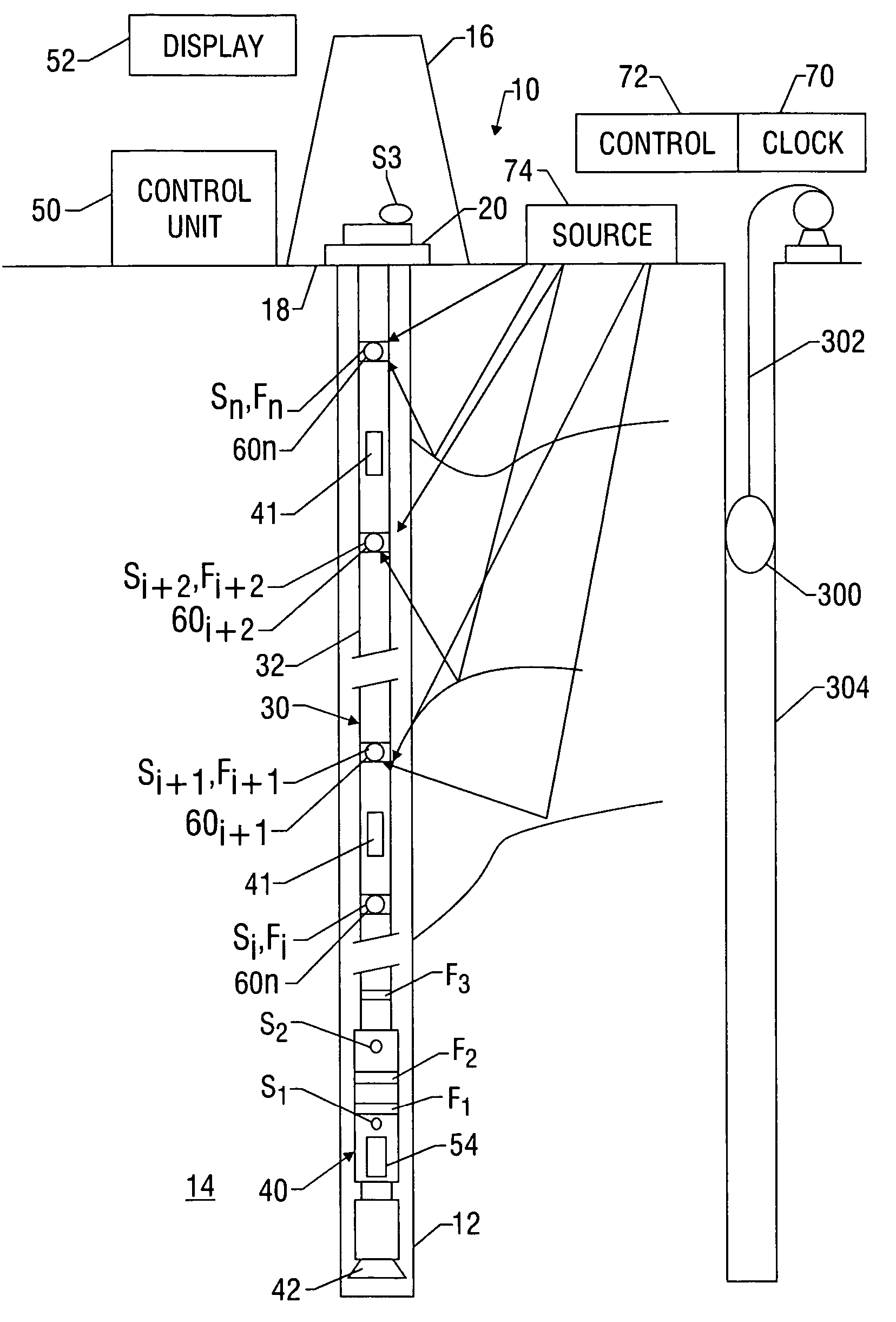
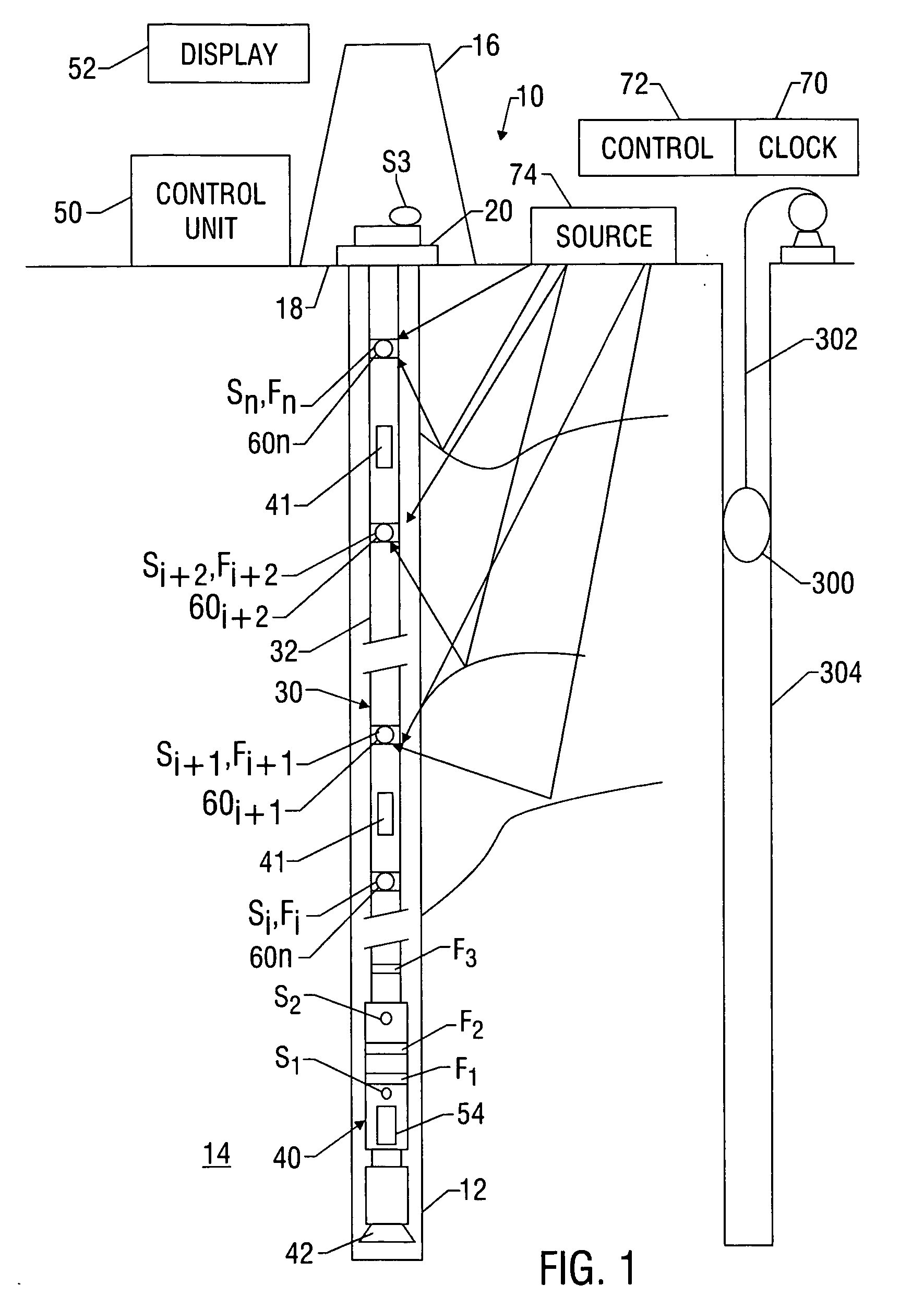
[0010] In one aspect, the present invention provides a drilling
system including a derrick erected on a floor and a drill string suspended therefrom. A bottomhole
assembly (BHA) operatively coupled to an end of the drill string includes a
drill bit and known components such as
wellbore pressure control devices, thrusters, mud motors, steering units and other known components. The drilling system also can include control units, such as a surface
control unit and a downhole control unit, that are programmed to perform any number of selected tasks; e.g.,
record and process data, control or assist in controlling drilling parameters and / or direction, and monitor drill string and BHA conditions. In one embodiment, the drill string includes sensors and devices that measure one or more selected parameters of interest from distributed locations along a section of a drill string. During construction of the well, these sensors provide measurements that can be used to improve drilling efficiency, enhance reliability of the various drilling system components, and increase the accuracy of
directional drilling. During
hydrocarbon production, the seismic data collected by the sensors can enhance the management and overall performance of the well.
[0015] In one aspect of operation, the downhole processors and the surface control
unit process data relating to the various types of parameters noted above and utilize the models to determine or compute the drilling parameters for continued drilling that will provide an enhanced
rate of penetration, extend drilling assembly life, provide more precise
geosteering, and result in greater wellbore stability. In another aspect of operation, pressure and density measurements from the distributed sensors can be used to control pressure in the wellbore, including the bottomhole pressure, during drilling of the wellbore. Based on this information, the control unit operates suitable
drilling fluid control devices to adjust the pressure and / or density profile such that a selected wellbore and / or bottomhole pressure is maintained at a selected condition (e.g., at-balanced, under-balanced, or over-balanced condition). In yet another aspect of operation, at least some of the distributed sensors are used to detect
seismic energy generated by a seismic source (either at the surface, in the same well or in an offset well). Advantageously, in embodiments of the present invention, the distributed sensors can detect
seismic energy in a number of operating scenarios: e.g., when the drill string is being rotated, when the drill string is not being rotated, when the
drilling fluid is being circulated, when the
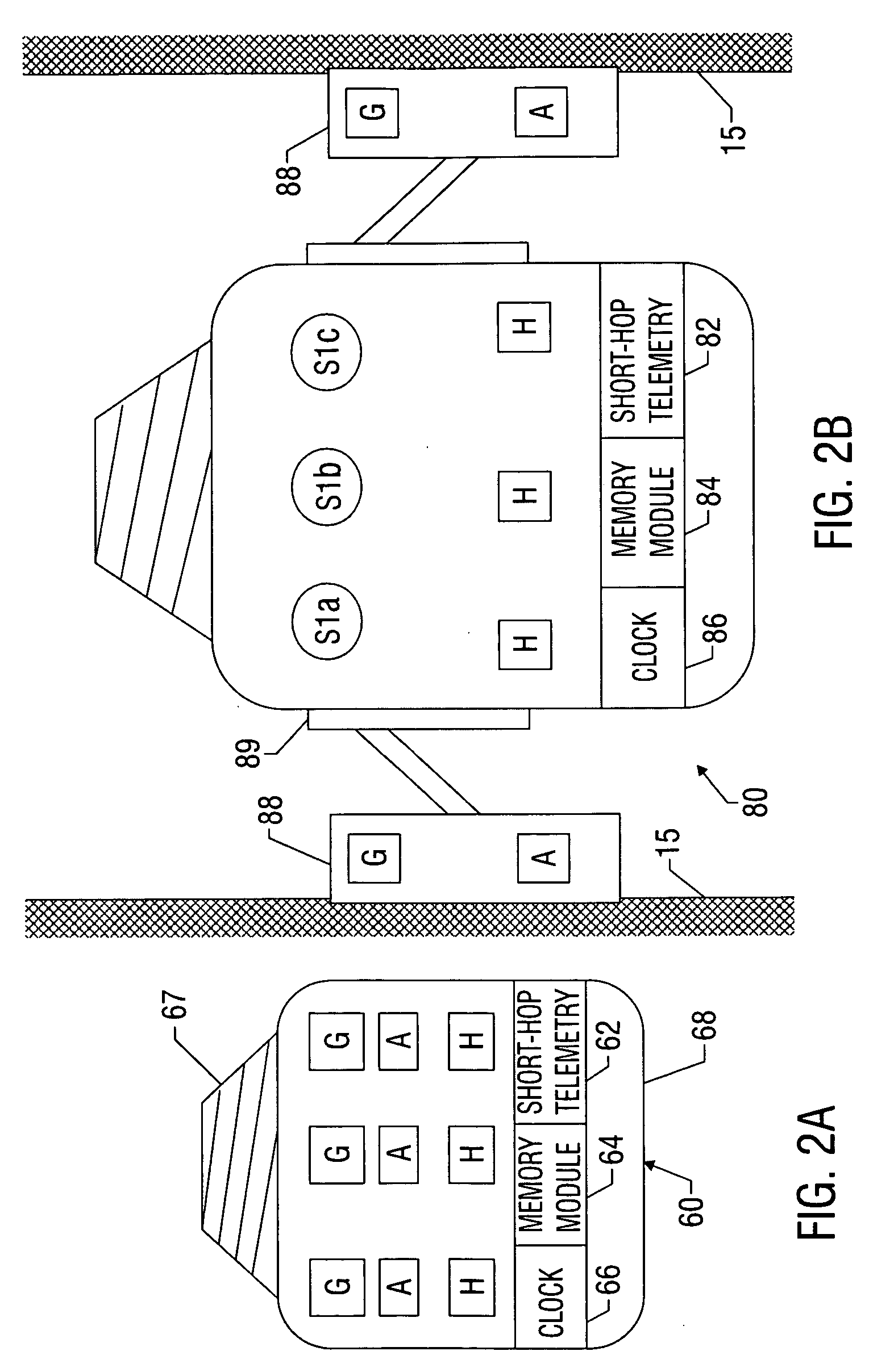
drilling fluid is not being circulated, when the BHA and drill bit at bottom, and / or when the BHA and drill bit are off-bottom. The seismic sensors, which are strategically positioned in a distributed fashion along a specified span of the wellbore, collect seismic data that is “time stamped” with the downhole
clock, processed and transmitted to the processors (surface control unit or a downhole processor). In one mode, the processed data is transmitted to an adjacent receiver (either upstream or downstream) for further
processing and re-transmission. The data can also be stored in a
memory module for later retrieval. The processors enter the seismic data into a model or
database, which then is used for reservoir mapping and / or more accurate
geosteering.

