Rectenna

Inactive Publication Date: 2014-01-02
IHI AEROSPACE CO LTD
View PDF11 Cites 239 Cited by
  • Summary
  • Abstract
  • Description
  • Claims
  • Application Information

AI Technical Summary

Benefits of technology

[0008]The present invention was made to solve the above problem, and an object thereof is to prov

Problems solved by technology

However, the technique disclosed in the above literature requires a physical space that allows the

Method used


Image

  • Rectenna
  • Rectenna
  • Rectenna

Examples


Embodiment Construction

[0018]An embodiment of the present invention will be described below with reference to the drawings.

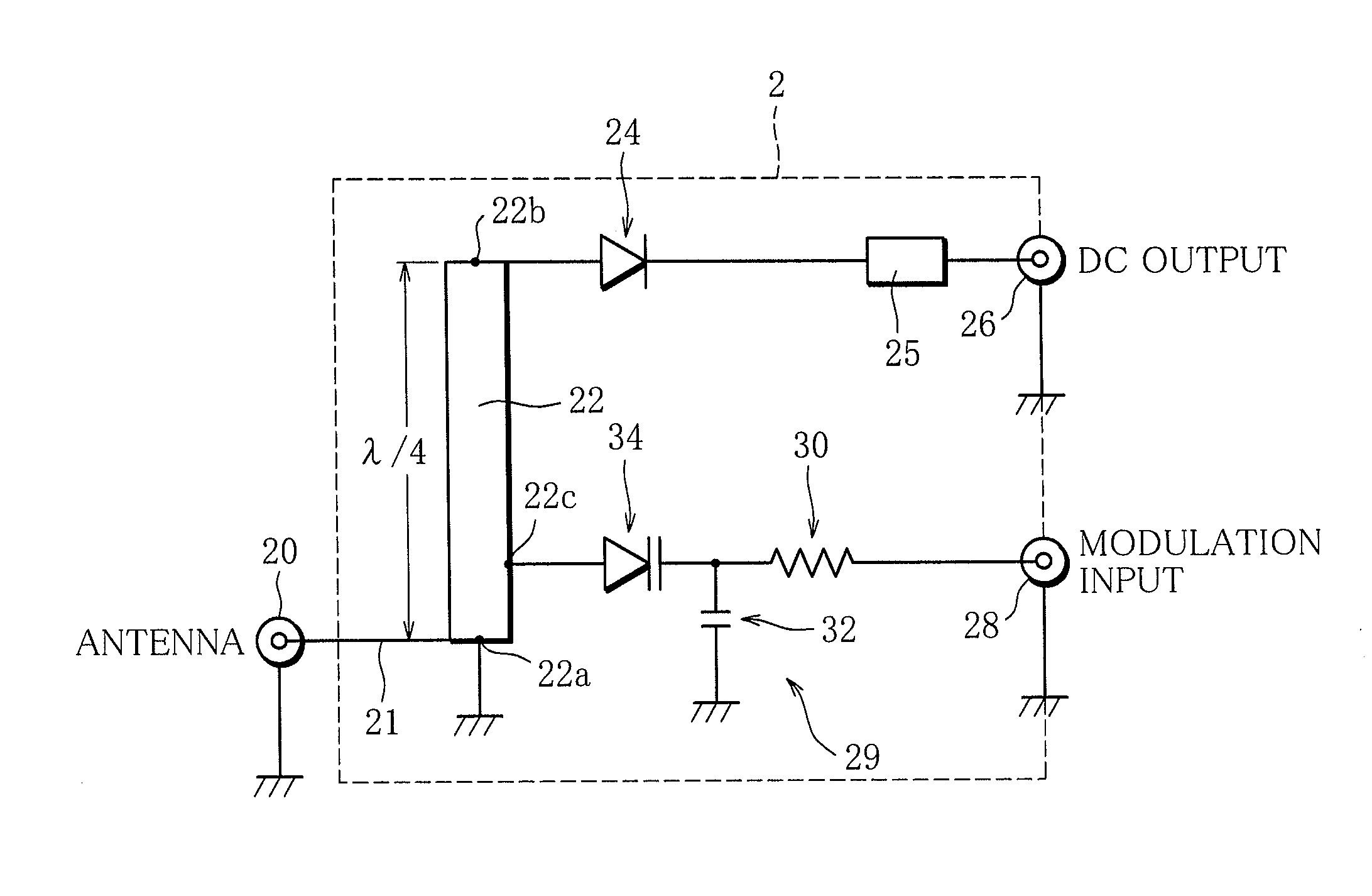
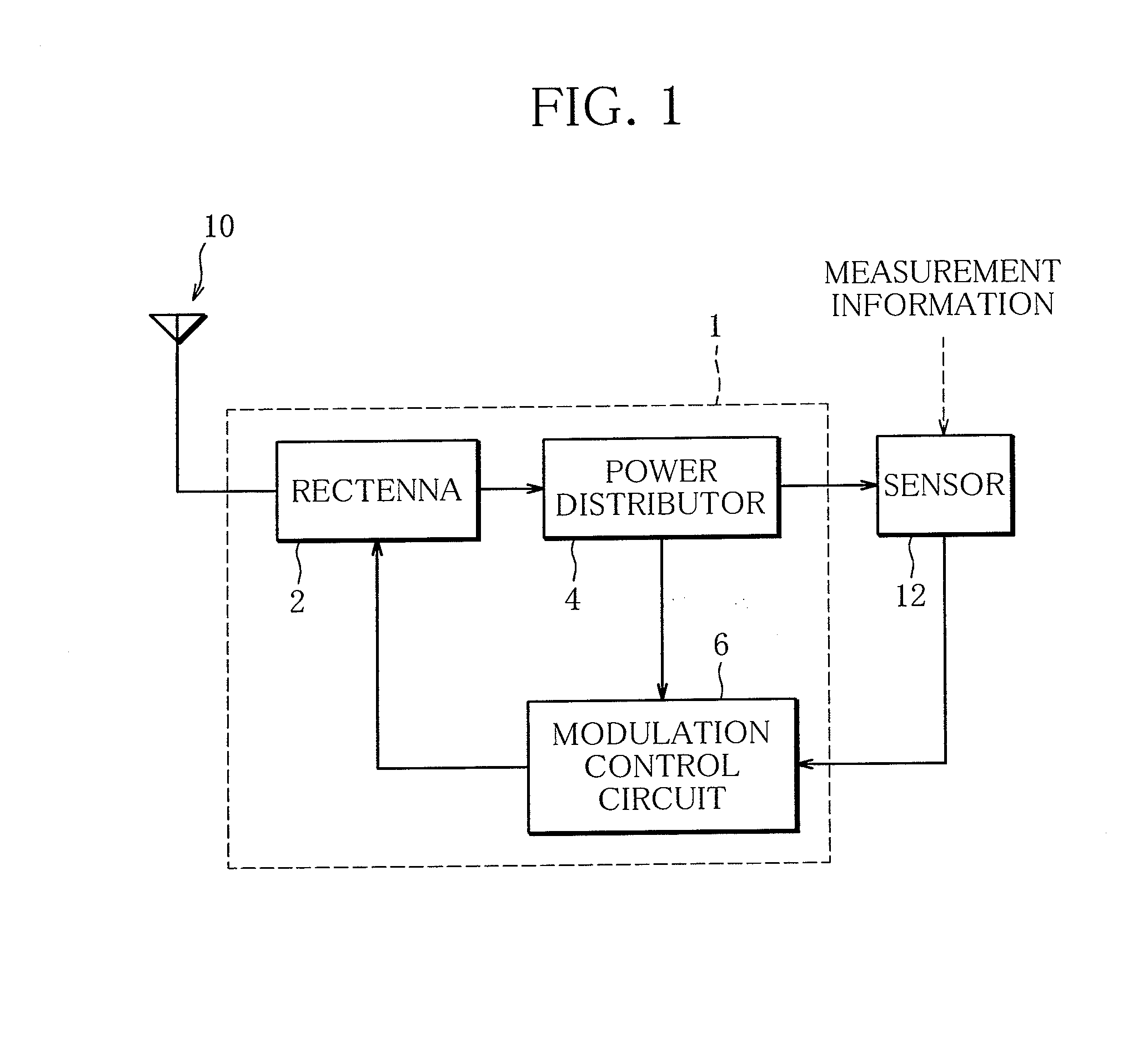
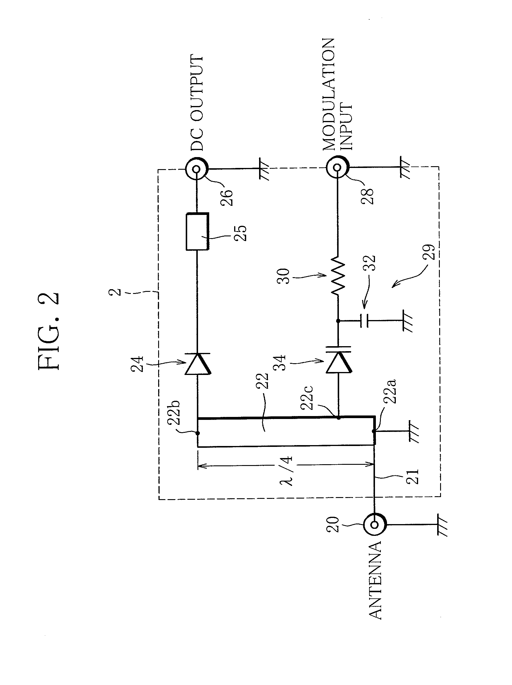
[0019]FIG. 1 schematically illustrates a high-frequency circuit provided with a rectenna according to the present invention. The high-frequency circuit 1 includes a rectenna 2, an electrical power distributor 4, and a modulation control circuit 6. The rectenna 2, which is connected with an antenna 10, rectifies a microwave (hereinafter referred to as carrier wave) received by the antenna 10 to convert the received carrier wave into a direct current and supplies the direct current to the power distributor 4. The frequency band of the carrier wave received by the antenna 10 is, for example, 2.45 GHz band or 5.8 GHz band.

[0020]The power distributor 4 distributes the electrical power supplied thereto from the rectenna 2 to a sensor 12, which is connected to the high-frequency circuit 1, as well as to the modulation control circuit 6 connected to the power distributor 4 so that the modulat...


PUM


Abstract

A rectenna includes an antenna configured to receive a radio wave, a rectifier circuit configured to rectify the radio wave received by the antenna, a transmission line connected to the antenna and the rectifier circuit, and a modulation input circuit including a variable capacitance element. The variable capacitance element is connected at one end to a portion of the transmission line between an antenna connecting portion at which the antenna is connected to the transmission line and a rectifier circuit connecting portion at which the rectifier circuit is connected to the transmission line, and is configured such that the capacitance thereof varies in accordance with the voltage of a modulated signal wave input to the other end of the variable capacitance element.

Description

BACKGROUND OF THE INVENTION[0001]1. Field of the Invention[0002]The present invention relates to rectennas, and more particularly, to a rectenna for rectifying and converting radio waves into electrical power.[0003]2. Description of the Related Art[0004]Rectenna is a device that converts microwaves received by its antenna into direct current to obtain electrical power. Such rectennas are expected to be used for wireless power transmission, as in space solar power generation systems in which electricity is generated with the use of solar light collected by solar panels mounted on an artificial satellite and is transmitted to the ground in the form of microwaves, which are received on the ground and converted into electrical power, as well as in wireless power supplies for feeding electrical power to electric vehicles, mobile terminals and the like.[0005]In recent years, rectennas have come to be used in RFID (Radio Frequency Identification) chips for the purpose of rectification. An ...

Claims


Application Information

Patent Timeline
IPC IPC(8): H02J17/00
CPCH02J17/00H01Q1/2225H01Q1/248H02J50/27
Inventor FUJIWARA, EIICHIRO FUJIWARAAOKI, MASARU
Owner IHI AEROSPACE CO LTD
Why Eureka
Try Eureka